6HFWLRQ_
06HULHV__5HY__HPDLOSVG#SÁRZFRP
Section 9 |
Sequence of Operation
www.pflow.com
P 414 352 9000
F 414 352 9002
6720 N. Teutonia Ave.
Milwaukee, WI 53209
Begin Sequence
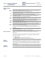
Push-button Station Figure 9-1
Control Panel Example Figure 9-2
Limit Switch / Cam Figure 9-3
1. Transformer
2. Motor Starter
3. Overload
4. Control Relays
5. Fuse
6. Over Current Sensor
7. Terminal Block
5
5
5
7
7
7
1
6
2
3
4
J16268-0050-01.DWG
PFL-1428-1
UPPER
LEVEL
LIMIT
SWITCH
15690-1001-S.SMG
PFL-1101
1. Press the desired floor level button. See Figure 9-1. The coil in the motor
starter magnetically closes the high voltage contacts and the power circuit
to the motor starter. See Figure 9-2. This action turns the motor in the
needed direction.
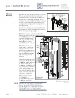
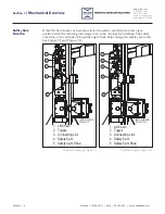
2. The brake is released. The motor turns the gears in the reducer, which in
turn rotates the keyed drive shaft. The drive sprockets on the shaft turn
resulting in the raising or lowering of the lift chains. The lift chains are
fastened to the safety cam assemblies, which are bolted to the carriage
uprights. Adjustments to the safety cam assembly levels the carriage deck.
3. When the carriage arrives at the next level, the floor level limit switch is
activated by a carriage mounted cam. See Figure 9-3. When the floor limit
switch is activated, the switch cuts the power to the motor circuit. The
motor starter contacts open, the motor stops, and the brake is applied. This
stops and holds the carriage position.
13675-0002.SMG
PFL-200115-3


