4
20
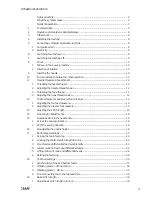
Presser foot settings ...................................................................................................... 38
.1
Clearance between presser foot and needle plate ......................................................... 38
.2
Presser foot stroke with the automatic presser foot lifter ............................................. 38
.3
Aligning the presser foot ................................................................................................ 40
21
Hook settings ................................................................................................................. 42
.1
Hook - lateral motion ...................................................................................................... 42
.2
Adjusting the hook height .............................................................................................. 44
.3
Adjusting the hook angle ................................................................................................ 46
.4
Hook-to-needle clearance in sewing direction ................................................................ 46
.5
Hook-to-needle clearance in hook direction (across the sewing direction) ..................... 46
.6
Hook motion .................................................................................................................. 48
.7
Needle height and hook-to-needle clearance ................................................................. 50
22
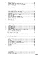
Rear needle guard .......................................................................................................... 52
.1
Adjusting the height of the rear needle guard ................................................................ 52
.2
Clearance between rear needle guard and needle ......................................................... 52
23
The hook-eccentric guard ............................................................................................... 52
24
Front needle guard ......................................................................................................... 54
.1
Adjusting the height ....................................................................................................... 54
.2
Lateral adjustment ......................................................................................................... 54
25
Needle thread puller ....................................................................................................... 56
26
Needle thread regulator ................................................................................................. 56
27
Adjustable thread guide ................................................................................................. 56
28
Hook thread regulator .................................................................................................... 58
29
Hook thread controller .................................................................................................... 58
30
Hook thread puller .......................................................................................................... 58
31
Quick adjustment of the differential for altering the gathering intensity ........................ 60
.1
Zeroing the differential quick adjustment ....................................................................... 60
.1.1 Rough adjustment at the Angle transmitter ................................................................... 60
.1.2 Fine adjustment at the poti “0” ..................................................................................... 60
.2
Key allocation for positioning the cam against the actuating lever ................................. 62
.2.1 Setting the gathering level of key “1” ............................................................................ 62
.2.2 Setting the gathering levels ........................................................................................... 62
32
Edge trimmer ................................................................................................................. 64
.1
Trimming motion ............................................................................................................ 64
.2
Zero point ....................................................................................................................... 64
.3
Knife height .................................................................................................................... 64
.4
Aligning the upper knife in sewing direction .................................................................. 66
.5
Aligning the upper knife across the sewing direction ..................................................... 66
.6
Aligning the stop eccentric ............................................................................................. 66
33
Tape brake ..................................................................................................................... 68
.1
Switching on .................................................................................................................. 68
.2
Switching off .................................................................................................................. 68
.3
Adjusting the brake intensity .......................................................................................... 68
.4
Pre-tension ..................................................................................................................... 68
34
Care and maintenance ................................................................................................... 70
.1
Sewing machine ............................................................................................................ 70
.2
Maintenance unit ........................................................................................................... 70
.3
Lubrication recommendation .......................................................................................... 71
Summary of Contents for 3811-11/43
Page 9: ...9 1 1 2 3 1 Bi34 01 CDR 2 4 3 Bi03 03 CDR ...
Page 11: ...11 4 1 Min Oil level Max Oil level 1 2 Bi08 01 Bi18 05 Bi08 04 CDR Bi02 01 3 ...
Page 13: ...13 3 2 1 4 1 Bi11 01 CDR 2 3 Bi11 02 Bi11 04 Bi11 03 ca 7cm ...
Page 15: ...15 2 Bi12 02 CDR Bi12 03 CDR 3 6 1 2 4 5 1 3 Bi12 01 CDR ...
Page 17: ...17 4 Bi14 04 5 Bi14 05 Schematic diagram 7 6 Bi14 03 3 6 4 5 7 4 7 5 0 8mm Bi14 02 CDR 2 3 ...
Page 19: ...19 Bi01 01 1 1 2 Bi16 02 CDR 11mm Bi14 03 3 1 2 ...
Page 21: ...21 5 Bi17 03 CDR 3 4 Bi17 04 CDR 2 Bi17 03 3 4 4 Bi17 05x CDR 5 ...
Page 27: ...27 18 Bi17 18 CDR 19 2x 18 17 20 2x 20 Bi17 20 CDR 17 19 2x 18 20 2x 19 Bi01 01 1 ...
Page 31: ...31 Bi18 16 Bi18 05 4 1 4 Bi01 01 16 5mm Bi18 17 CDR 3 2 2 1 3 1 2 ...
Page 39: ...39 Bi14 03 1 Bi14 03B 7mm 2 3 4 2 3 1 9 8 7 11 5 Bi20 03 CDR 10 10 5 1 6 ...
Page 43: ...43 1 Bi01 01 1 3 Bi17 20 CDR Bi20 02 CDR 1 2 1 2 2x ...
Page 49: ...49 Bi21 15 CDR 14 15 Bi21 16 CDR 16 Part No 08 880 137 00 Bi21 17 17 Bi17 04 CDR 20 21 2x ...
Page 51: ...51 Bi21 18 CDR 18 1 0 1 2mm Bi14 03 22 23 20 19 Bi21 19 CDR 0 1mm Hook ...
Page 53: ...53 Bi22 21 CDR Bi21 11 2 1 2 1 1 Bi01 01 3 3 Bi22 04 CDR 4 Bi22 05 5 6 Bi22 06 3 4 6 7 5 ...
Page 55: ...55 Bi24 01 CDR 1 2 Bi22 06 2 1 1 4 3 5 2 Bi24 04 CDR 0 3 0 5mm 3 4 1 ...
Page 57: ...57 0 3mm Bi25 01 1 1 2 Bi26 01 Bi26 02 2 3 3 1 3 4 Bi27 01 4 5 ...
Page 59: ...59 Bi29 04 CDR 5 4 1 3 4 Bi29 03 CDR 8mm 3 Bi28 01 1 1 2 5 4 3 6 Bi01 01 1 2 29mm ...
Page 63: ...63 7 6 5 Tastenfeld von 11 43 11 45 13 45 Bi31 02 CDR Bi19 04 CDR ...
Page 69: ...69 1 Bi33 01 CDR 3 1 2 4 Tastenfeld 11 43 11 45 13 45 2 Bi02 03 CDR ...

