60
31
Quick adjustment of the differential for altering the gathering
intensity
31.1
Zeroing the differential quick adjustment
31.1.1
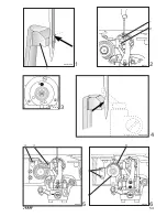
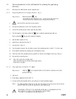
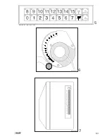
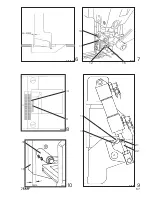
Rough adjustment at the angle encoder 1
(fig. 2)
Requirement:
After pressing the
key:
- the actuating lever 2 should be at “0” on the control cam scale, and
- the sewing machine should sew smoothly (without fullness).
.1
Switch off the machine (mains switch).
.2
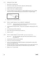
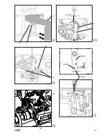
Remove the protective cover 1 from the angle encoder.
.3
Loosen the retaining screw of the angle encoder a little.
.4
Turn the machine on (mains switch): the
key is activated automatically (LED on).
On the -2/45 the
key must be activated manually.
.5
Set the stitch length at 4 mm.
.6
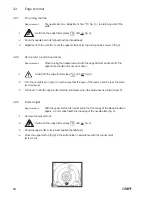
Attach the connecting rod 4 (fig. 3).
.7
Loosen screw 3 (fig. 2).
.8
Turn the angle encoder 1 (fig. 2) until the roller on the actuating lever 2 is at the “0” on the scale.
.9
In this position, tighten the retaining nut on the angle encoder.
.10
Place the roller of the actuating lever 2 against the control cam and tighten the screw 3 (fig. 3).
.11
Remove the connecting rod 4.
.12
- Carry out a control (see requirement)
- Screw the protective cover back on the angle encoder
- Mount the cover plate.
31.1.2
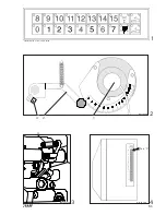
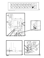
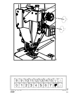
Fine adjustment at the Poti 0
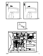
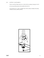
(fig.4)
Requirement:
When the
key is activated (LED on), the machine should sew smoothly
(without fullness).
.1
Test seam
.2
If necessary, adjustment at the Poti “0”.
.3
To carry out the fine adjustment the connecting rod 4 must be attached again.
Note:
The default setting of the Poti “0” (fig. 4) is the position “0” and as a rule it should not be
altered or altered very little (for altering the rough adjustment)!
Nevertheless, if the Poti “0” should be altered strongly, a rough adjustment of the
basic setting (“0” position of the Poti) can be made as follows:
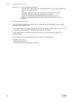
- Turn Poti “0” 20 rotations to the left (direction -).
Summary of Contents for 3811-11/43
Page 9: ...9 1 1 2 3 1 Bi34 01 CDR 2 4 3 Bi03 03 CDR ...
Page 11: ...11 4 1 Min Oil level Max Oil level 1 2 Bi08 01 Bi18 05 Bi08 04 CDR Bi02 01 3 ...
Page 13: ...13 3 2 1 4 1 Bi11 01 CDR 2 3 Bi11 02 Bi11 04 Bi11 03 ca 7cm ...
Page 15: ...15 2 Bi12 02 CDR Bi12 03 CDR 3 6 1 2 4 5 1 3 Bi12 01 CDR ...
Page 17: ...17 4 Bi14 04 5 Bi14 05 Schematic diagram 7 6 Bi14 03 3 6 4 5 7 4 7 5 0 8mm Bi14 02 CDR 2 3 ...
Page 19: ...19 Bi01 01 1 1 2 Bi16 02 CDR 11mm Bi14 03 3 1 2 ...
Page 21: ...21 5 Bi17 03 CDR 3 4 Bi17 04 CDR 2 Bi17 03 3 4 4 Bi17 05x CDR 5 ...
Page 27: ...27 18 Bi17 18 CDR 19 2x 18 17 20 2x 20 Bi17 20 CDR 17 19 2x 18 20 2x 19 Bi01 01 1 ...
Page 31: ...31 Bi18 16 Bi18 05 4 1 4 Bi01 01 16 5mm Bi18 17 CDR 3 2 2 1 3 1 2 ...
Page 39: ...39 Bi14 03 1 Bi14 03B 7mm 2 3 4 2 3 1 9 8 7 11 5 Bi20 03 CDR 10 10 5 1 6 ...
Page 43: ...43 1 Bi01 01 1 3 Bi17 20 CDR Bi20 02 CDR 1 2 1 2 2x ...
Page 49: ...49 Bi21 15 CDR 14 15 Bi21 16 CDR 16 Part No 08 880 137 00 Bi21 17 17 Bi17 04 CDR 20 21 2x ...
Page 51: ...51 Bi21 18 CDR 18 1 0 1 2mm Bi14 03 22 23 20 19 Bi21 19 CDR 0 1mm Hook ...
Page 53: ...53 Bi22 21 CDR Bi21 11 2 1 2 1 1 Bi01 01 3 3 Bi22 04 CDR 4 Bi22 05 5 6 Bi22 06 3 4 6 7 5 ...
Page 55: ...55 Bi24 01 CDR 1 2 Bi22 06 2 1 1 4 3 5 2 Bi24 04 CDR 0 3 0 5mm 3 4 1 ...
Page 57: ...57 0 3mm Bi25 01 1 1 2 Bi26 01 Bi26 02 2 3 3 1 3 4 Bi27 01 4 5 ...
Page 59: ...59 Bi29 04 CDR 5 4 1 3 4 Bi29 03 CDR 8mm 3 Bi28 01 1 1 2 5 4 3 6 Bi01 01 1 2 29mm ...
Page 63: ...63 7 6 5 Tastenfeld von 11 43 11 45 13 45 Bi31 02 CDR Bi19 04 CDR ...
Page 69: ...69 1 Bi33 01 CDR 3 1 2 4 Tastenfeld 11 43 11 45 13 45 2 Bi02 03 CDR ...

