background image

Safety

1 - 4

1

.06

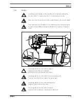
Danger

A working area of 

1 meter

 is to be kept free both in front of and behind the

machine while it is in operation so that it is always easily accessible.

Never reach into the sewing area while sewing! Danger of injury by the needle!

Never leave objects on the table or in the needle plate area while adjusting the

machine settings! Objects can become trapped or be slung away! Danger of

injury!

Do not operate the machine without support 

1

!

Danger due to top-heavy sewing head!

Machine can tip over backwards when tilted!

Do not operate the machine without its take-up-lever guard 

2

!

Danger of injury due to the motion of the take-up lever!

Do not operate the machine without belt guards 

3

!

Danger of injury by the moving V-belt!

Do not operate the machine without tilt lock 

4

!

Danger of crushing between sewing head and table top!

2

3

Fig. 1 - 01

1

4

Summary of Contents for 3734-2/01

Page 1: ...296 12 18 352 002 Betriebsanleitung engl 05 2002 Instruction Manual This instruction manual applies to machines from the following serial numbers onwards 2207198 3734 2 01 2 21 ...

Page 2: ...s whether in whole or in part is only permitted with our previous authorisation and with written reference to the source PFAFF Industrie Maschinen AG Postfach 3020 D 67653 Kaiserslautern Königstr 154 D 67655 Kaiserslautern Redaktion Illustration VTD GmbH D 77901 Lahr ...

Page 3: ... within the customer s premises 5 1 5 03 Disposal of the packaging 5 1 5 04 Storage 5 1 6 Explanation of the symbols 6 1 7 Controls 7 1 7 01 On off switch 7 1 7 02 Pedal 7 1 7 03 Knee switch 7 2 7 04 Lever for lifting the roller presser 7 2 7 05 Control panel 7 3 7 05 01 Displays on the screen 7 3 7 05 02 Key functions 7 3 8 Mounting and commissioning the machine 8 1 8 01 Mounting 8 1 8 01 01 Adju...

Page 4: ...1 Notes on adjusting 12 1 12 02 Tools gauges and other accessories for adjusting 12 1 12 03 Abbreviations 12 1 12 04 Adjusting the basic machine 12 2 12 04 01 Adjusting the synchronizer 12 2 12 04 02 Positioning the needle in the direction of sewing 12 3 12 04 03 Positioning the needle across the direction of sewing 12 4 12 04 04 Preadjusting the needle height 12 5 12 04 05 Needle rise hook to nee...

Page 5: ...position of the control cam to the bobbin opener adjustment without adjustment gauge 12 28 12 05 08 Scissor tripping lever in relation to the control cam of the scissor 12 29 12 05 09 Control cam to cutter adjustment without adjustment gauge 12 30 12 05 10 Scissor return lever 12 31 12 05 11 Scissor return control 12 32 12 05 12 Installing the scissor 12 33 12 05 12 Eccentric sleeve 12 34 12 05 14...

Page 6: ...ng sewing tools e g needle roller presser needle plate or bobbin when threading the machine when leaving the machine unattended and during maintenance work the machine is to be separated from the power supply by switching off the On Off switch or by removing the plug from the mains Everyday maintenance work is only to be carried out by appropriately trained personnel Repairs and special maintenanc...

Page 7: ...sonnel is to be instructed as to the safety equipment of the machine and regarding safe work methods It is the duty of the user to only operate the machine in perfect running order It is the obligation of the user to ensure that none of the safety mechanisms are removed or deactivated It is the obligation of the user to ensure that only authorized persons operate and work on the machine Further in...

Page 8: ...lways immediately report to the person responsible any changes in the machine which may limit its safety 1 05 02 Specialist personnel Specialist personnel are persons with a specialist education in the fields of electrics electronics and mechanics They are responsible for the lubrication maintenance repair and adjustment of the machine The specialist personnel is obliged to observe the following p...

Page 9: ... the machine settings Objects can become trapped or be slung away Danger of injury Do not operate the machine without support 1 Danger due to top heavy sewing head Machine can tip over backwards when tilted Do not operate the machine without its take up lever guard 2 Danger of injury due to the motion of the take up lever Do not operate the machine without belt guards 3 Danger of injury by the mov...

Page 10: ... forwards and reverse feeding feed wheel and band feed This machine is used for sewing lockstitch seams in the clothing industry Any and all uses of this machine which have not been approved of by the manufacturer are considered to be inappropriate The manufacturer cannot be held liable for any damage caused by the inappropriate use of the machine The appropriate use of the machine includes the ob...

Page 11: ...ng voltage 230 V 10 50 60 Hz Max power consumption 1 2 kVA Fuse protection 1 x 16 A inert Noise data Emission sound level at the workplace at a speed of 2700 spm 80 dB A Noise measurement in acc with DIN 45 635 48 A 1 ISO 11204 ISO 3744 ISO 4871 Net weight of sewing head approx 61 kg Gross weight of sewing head approx 71 kg Subject to alternation Varies according to material work process and stitc...

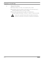
Page 12: ...ous plastics The electrical equipment consists of plastics and copper The machine is to be disposed of in accordance with the locally valid environmental protection regulations If necessary a specialist is to be commissioned Special care is to be taken that parts soiled with lubricants are separately disposed of in accordance with the locally valid pollution control regulations 4 1 ...

Page 13: ...hin the customer s premises or to the individual locations of use Always ensure that the machine is only transported upright 5 03 Disposal of the packaging The packaging of these machines consists of paper cardboard and VCE fibre The proper disposal of the packaging is the responsibility of the customer 5 04 Storage The machine can be stored for up to 6 months if not in use During this time it sho...

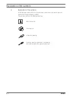
Page 14: ...f this Instruction Manual certain tasks or important pieces of information are accentuated by symbols The symbols used have the following meanings Note information Cleaning care Lubrication greasing Servicing repairing adjustment maintenance only to be carried out by specialist personnel ...

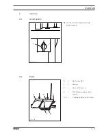
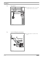
Page 15: ...s 7 01 On off switch Turn the machine on off by turning On Off switch 1 0 1 7 02 Pedal 0 Neutral position 1 Sewing 2 Raise roller presser 3 Trim thread and raise roller presser 1 4 Variable application of fullness Fig 7 02 4 0 1 3 2 ...

Page 16: ...2 7 04 Lever for lifting the roller presser The roller presser is raised by turning lever 1 7 03 Knee switch By operating knee switch 1 it is possible to select 2 pre set values for fullness Fig 7 03 1 Fig 7 04 1 ...

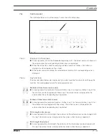
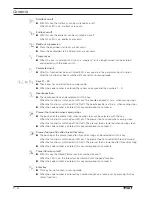
Page 17: ...Starttack stitches forwards in reverse In sewing mode the number of forward stitches key A or reverse stitches key B for the starttack can be changed with these keys The current value is displayed on the screen when the corresponding key is operated Endtack stitches forwards in reverse In sewing mode the number of reverse stitches key C or forward stitches key D for the endtack can be changed with...

Page 18: ... b d c when sewing stops When the code number is entered this key corresponds to number 6 Presser foot position when sewing stops The position of the presser foot when sewing stops can be selected with this key When the function is switched on LED on The presser foot is raised when sewing stops When the function is switched off LED off The presser foot is lowered when sewing stops When the code nu...

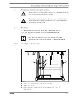
Page 19: ...r even while sewing 8 01 Mounting The necessary electricity supply must be available at the machine s location There must be a stable and horizontal surface and adequate lighting at the machine s location Due to reasons of packaging the table top is lowered for transport The following is a description of how to adjust the height of the table top 8 01 01 Adjusting the table top height Loosen screws...

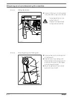
Page 20: ...e heads of mounting screws 4 and fasten with screws 5 Then tighten screws 4 through the holes Mount the right and left halves of belt guard with screws 6 and 7 1 2 4 4 6 6 7 7 5 3 Fig 8 02 8 01 02 Fitting the tilt lock Screw on tilt lock parts 1 and 2 provided in the accessories using screws 3 and 4 Do not operate the machine without tilt lock 1 Danger of crushing between sewing head and table top...

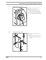
Page 21: ...ly Plug the synchronizer plug into the electrical socket of the control box Adjust the synchronizer see chapter 12 04 01 Adjusting the synchronizer Fig 8 04 2 1 8 01 05 Mounting the spool holder Mount the spool holder as shown in Fig 8 07 Insert the spool holder into the hole in the table top and affix it with the nuts enclosed Fig 8 05 ...

Page 22: ...erated with the available electricity supply and that it is connected correctly to the terminal box If not do not operate the machine under any circumstances 8 03 Switching the machine on off Switch on the machine see Chapter 7 01 On off switch 8 01 06 Attaching the earthing wire connecting the plug connections Fig 8 06 Screw the earthing wires from the sewing head the main switch and the control ...

Page 23: ...ng off the On Off switch 9 01 Inserting the needle Turn the machine off Use only system 134 35R needles Raise roller presser or band feed 1 Pull roller presser or band feed 1 down slightly and swing it to the left Pull roller presser 1 downwards slightly and swing it out to the left Loosen screw 2 and insert needle 3 until you feel it stop The long groove must be facing the left Tighten screw 2 an...

Page 24: ...obbin 1 a few times Switch on the bobbin winder by pressing the bobbin winder spindle 2 and lever 3 at the same time The bobbin fills up while you are sewing The tension of the thread on bobbin 1 can be adjusted with knurled screw 4 The bobbin winder stops automatically when bobbin 1 is full If the thread is wound unevenly Loosen nut 5 Turn thread guide 6 accordingly Tighten nut 5 2 1 4 _ Fig 9 02...

Page 25: ...g Inserting the bobbin case Turn the machine off Removing the bobbin case Open the post cap Raise latch 1 and remove bobbin case 2 Inserting the bobbin case Insert bobbin case 2 Close the latch and close the post cap Fig 9 03 2 1 ...

Page 26: ...d tension Insert the bobbin into the bobbin case 1 Pass the thread through the slot under spring 2 Pass the thread through the notch Adjust the thread tension by turning screw 3 When the thread is pulled the bobbin must rotate in the direction of the arrow 2 1 5 c m Fig 9 04 ...

Page 27: ...n 9 05 Threading the needle thread adjusting the needle thread tension Switch off the machine Thread needle thread as shown in Fig 9 05 Adjust the needle thread tension by turning knurled screws 1 and 2 Fig 9 05 1 2 ...

Page 28: ...e Set the stitch length feed stroke of the roller presser by pressing key P Set the stitch length feed stroke of the feed wheel by pressing key L 9 06 02 Entering a second stitch length fullness With the program key a second fullness setting can be stipulated in addition to the standard setting When the program key is activated it is possible to switch from one fullness to the other using the knee...

Page 29: ...s range which can be selected using the left pedal Switch on the machine Press the Parameter input key LED on By pressing Key A select the parameter 100 with By pressing Key B select the parameter 103 with By pressing Key L enter the required value with Press the Parameter input key LED off 103 4 0 103 3 5 100 ...

Page 30: ...the plus minus key Confirm input By pressing the key A B select the parameter 809 with By pressing the appropriate keys enter the new code number Save input by ending the parameter input LED off Enter the code number factory code setting is 1493 When entering the code number these keys correspond to the number above them 1 2 6 5 4 3 7 8 9 100 CODE 0 809 801 ...

Page 31: ... If necessary change the amount of fullness see Chapter 9 06 01 Standard stitch length fullness The second amount of fullness can be selected by operating the knee switch when the program key is activated LED on Also see Chapter 9 06 02 Entering a second stitch length fullness The sewing functions are selected with the right pedal see Chapter 7 02 Pedal To adjust the variable fullness within a spe...

Page 32: ... than this shorter intervals are recommended 11 01 Cleaning Clean the hook and hook compartment daily more often if in continuous operation Turn the machine off Bring the needle bar to its highest position Open the post cap and remove the bobbin case cap and the bobbin Unscrew hook gib 1 Turn the handwheel until the point of bobbin case 2 penetrates into groove approx 5 mm Remove bobbin case 2 Cle...

Page 33: ...e only oil with a mean viscosity of 22 0 mm2 s at 40 C and a density of 0 865 g cm3 at 15 C We recommend PFAFF sewing machine oil Part no 280 1 120 144 11 2 11 02 Lubricating the hook Turn the machine off Apply 1 2 drops of oil into hole 1 of the hook gib every day Before commissioning and after longer standstill periods also apply a few drops of oil into the hook race see arrow in Fig 11 02 Fig 1...

Page 34: ...sh a little grease onto all of the tooth flanks and the rack see arrows To stand the machine head up again press safety plate 1 to the rear and stand the machine head up using both hands Fig 11 04 1 Use both hands to return the machine to an upright position Danger of crushing between machine head and table top We recommend PFAFF hard soap grease with a drop point of approx 150 C Part no 280 1 120...

Page 35: ...served Screws nuts indicated in brackets are fastenings for machine parts which must be loosened before adjustment and tightened again afterwards 12 02 Tools gauges and other accessories for adjusting 1 set of screwdrivers with blade widths from 2 to 10 mm 1 set of wrenches with jaw widths from 7 to 13 mm 1 set of Allan keys from 1 5 to 6 mm 1 adjustable clamp Part No 08 880 137 00 1 metal rule Pa...

Page 36: ...Fig 12 01 Switch on the machine and sew a few stitches Press the Parameter input key LED on By pressing Key A select the parameter 600 with Press Key B enter code By pressing Key B select the parameter 603 with Press on key L machine sews one stitch Loosen screws 1 Secure synchronizer 2 and adjust the needle bar by turning the balance wheel in accordance with the requirement Tighten screws 1 and s...

Page 37: ...quirement The needle must penetrate the middle of the needle hole as viewed in the direction of sewing Fig 12 02 Move the needle bar frame 1 screws 2 and 4 and nut 3 in accordance with the requirement Screws 4 are accessible through the holes on the back of the housing 3 2 4 1 3 ...

Page 38: ...ewing Requirement The needle must penetrate the middle of the needle hole as viewed across the direction of sewing Fig 12 03 Move the feed wheel post 1 screws 2 3 and 4 in accordance with the requirement Screws 4 remain loosened for the following adjustments 3 1 2 2 4 4 4 4 ...

Page 39: ...the needle height Requirement With the needle bar at TDC there must be approx 22 mm between the point of the needle and the needle plate Fig 12 04 Move the needle bar 1 screw 2 in accordance with the requirement without turning it 1 2 22 mm ...

Page 40: ...ement 2 Adjust the hook post according to requirement 1 and tighten screws 4 12 04 05 Needle rise hook to needle clearance needle height and needle guard Requirement When the needle bar is positioned at 1 8 mm after b d c 1 The point of the hook must be pointing to the centre of the needle and have a clearance of 0 05 0 1 mm to the needle 2 The top edge of the needle eye must be 0 8 1 00 mm below ...

Page 41: ...hole 5 Install the retaining collar 6 on bevel gear 7 and tighten screws 1 and 3 Tighten screws 8 on both sides of the post Align needle guard 9 in accordance with requirement 3 When changing the hook care must be taken to ensure that the markings 10 and 11 are on one side Fig 12 05 3 2 7 6 2 1 8 8 4 4 5 11 10 9 ...

Page 42: ...6 Bobbin case opener height Requirement The top edges of the bobbin case opener 1 and the bobbin case base 3 must be at the same height Move the bobbin case base 1 screws 2 in accordance with the requirement Fig 12 06 3 1 1 2 ...

Page 43: ...ase must protrude 0 3 0 5 mm from the rear edge of the needle plate recess Turn the handwheel until the bobbin case opener presses against the bobbin case to the furthest extent Move the bobbin case base screw 1 accessible from the rear of the post in accordance with the requirement This setting can vary according to the thickness of the thread 1 Fig 12 07 0 3 0 5 mm ...

Page 44: ...he feed wheel should project approx 0 8 mm from the needle plate and 0 4 mm on the 3734 2 21 Swing out the roller presser Loosen screw 1 Turn the eccentric screw 3 which is accessible through hole 2 in accordance with the requirement Tighten screw 1 1 2 3 Fig 12 08 0 4 0 8 mm ...

Page 45: ...nt When lever 1 is raised there should be a clearance of 7 mm between the roller presser and the feed wheel or the band feed Raise lever 1 Move the presser foot bar screws 2 in accordance with the requirement Take care to ensure that the roller presser is parallel to the feed wheel Fig 12 09 2 1 7 mm 7 mm ...

Page 46: ...e as possible to the needle when viewed across the direction of sewing Raise the roller presser 1 Always observe requirement 1 when carrying out the following adjustments Move the roller presser 1 screw 2 in accordance with requirement 2 Allow the roller presser 1 to come to rest on the feed wheel 5 Move the roller presser bracket 3 screw 4 in accordance with requirement 3 When sewing very tight c...

Page 47: ...ler 6 is approx 2 5 mm from the centre of feed wheel 7 2 The band feed 5 seen in the direction of sewing is parallel to feed wheel 7 and the seam runs directly below O ring 8 Adjust holder 1 screw 2 in accordance with requirement 1 Adjust holder 3 screw 4 in accordance with requirement 2 Fig 12 10a 1 2 4 3 6 7 5 8 9 10 ...

Page 48: ... 14 12 04 12 Changing the band 3734 2 21 Turn eccentric 1 screw 2 towards the inside Fit feed band 3 and tighten with eccentric 1 Tighten screw 2 Part no Feed band 91 189 210 95 0 ring 15 120 723 05 Fig 12 10b 1 2 3 ...

Page 49: ...op automatically 1 2 Move solenoid 1 screws 2 in accordance with the requirement Turn the machine on and check the requirement Turn the machine off Depending on the thickness of the material the clearance between the roller presser and the feed wheel can be increased to a maximum of 10 mm by moving the solenoid to the right Fig 12 11 3 ...

Page 50: ... 12 16 12 04 14 Retainer Requirement The retainer 3 should just rest on the material so that the material does not start fluttering during sewing Adjust pin 1 screw 2 according to the requirement Fig 12 12 1 2 3 ...

Page 51: ... both tension discs 6 must be at least 0 5 mm apart Raise the roller presser using lever 1 Adjust screw 2 nut 3 in accordance with the requirement Raise the roller presser using the automatic presser foot lifter or the knee lever Move the drive dog 4 screw 5 in accordance with the requirement Fig 12 13 0 5 mm 6 5 4 3 2 1 ...

Page 52: ...ust raise slightly from the workpiece rack 1 4 Fig 12 14 Move workpiece rack 1 screw 2 in accordance with requirement 1 Turn screw 3 screw 4 to adjust the strength of the spring Move the slack thread regulator 5 screw 6 in accordance with requirement 2 Due to technical sewing reasons it may be necessary to deviate from the spring stroke spring strength mentioned here Move the slack thread regulato...

Page 53: ...ith the bobbin winder off the friction wheel 5 must not engage the drive wheel 1 2 The bobbin winder must turn off automatically when the thread level is approx 1 mm from the edge of the bobbin 2 1 5 Fig 12 15 Move drive wheel 1 screws 2 in accordance with requirement 1 Move pin 3 screw 4 in accordance with requirement 2 1 mm 4 3 ...

Page 54: ... any pressure marks on the material Fig 12 16 Adjust the roller presser pressure with screw 1 in accordance with the requirement Screw 1 is underneath a cover When the pressure of the roller pressure is low the drop speed of the roller presser can be increased by activating the ROLLER PRESSER DROP SPEED function 1 ...

Page 55: ...1 12 04 19 Locking the set value transmitter Requirement The pedal for selecting the fullness should be held reliably in every position without binding too much Fig 12 17 Adjust screw 1 according to the requirement 1 ...

Page 56: ...ost cover 1 and unscrew post cover plate 2 screws 3 Loosen screw 4 Swing out bobbin case base 5 by hand and hold it in this position Remove bolt 6 Open the scissor drive bar and remove scissor 7 Allow bobbin case base 5 to swing in and close the scissor drive bar Post cover plate 2 remains dismounted for further adjustments ...

Page 57: ...ighten one of the screws 1 slightly so that control cam 2 can still be turned Loosen screw 4 Bring the needle bar to BDC and position the straight section of the cam track under the roller of tripping lever 6 Activate the engaging lever by hand Move tripping lever 6 together with schaft 7 in accordance with requirement 2 Taking care to ensure that connecting link 5 engages completely in the groove...

Page 58: ...nt With the tripping lever 3 in resting position there must be a clearance of 0 3 mm between its roller and the circumference of the control cam 4 Fig 12 20 Bring the needle bar to BDC Move solenoid carrier 1 nuts of screws 2 in accordance with the requirement 4 3 0 3 mm 2 1 ...

Page 59: ...e field core must still be 1 mm before its lower stop Fig 12 21 Bring the needle bar to BDC and activate the tripping lever by hand Push solenoid housing 1 screw 2 up as far as possible and then move it in accordance with the requirement Lift the tripping lever out of the control cam by hand 2 1 ...

Page 60: ...tment 12 26 2 1 9 mm Turn screw 1 nut 2 in accordance with the requirement Fig 12 22 12 05 05 Scissor drive lever Requirement The top edge of screw 1 must protrude approx 9 mm from the recess on the housing ...

Page 61: ...3 Loosen screws 1 and 2 Bring the needle bar to BDC and activate the tripping lever by hand roller 3 engaged Adjust the control cams in accordance with the requirement and insert adjustment gauge 5 Turn control curve 4 in accordance with the requirement Taking care to ensure that control cam 4 is touching the bearing collar tighten the accessible screws 1 and 2 Remove adjustment gauge 5 and tighte...

Page 62: ...er by hand While doing so the roller of the tripping lever 1 must drop into the cam track easily and without any impediment Bring the needle bar to 4 mm past b d c use the adjustment gauge and C clamp Turn control cam 3 in the sewing direction until you feel a resistance beginning of the retracting motion In this position tighten the accessible screw 2 Lift tripping lever 1 out of the control cam ...

Page 63: ...mm between the roller of tripping lever 4 and the external circumference of control cam 6 6 5 2 4 3 1 0 3 mm 6 4 Fig 12 26 Bring the needle bar to BDC and activate the tripping lever by hand Loosen screws 1 and 2 Turn the handwheel in the direction of rotation until rock shaft 3 is at its left point of reversal Move tripping lever 4 and back racking lever 5 in accordance with requirement 1 Turn tr...

Page 64: ...adjustment gauge and C clamp Turn control cam 2 until the trip is touching the roller of the tripping lever 3 Taking care that control cam 2 is 9 mm from retractor cam 4 tighten one of the screws 1 Remove the C clamp make the second screw 1 accessible and tighten it When using elastic sewing threads it can be necessary to set the relationship between the control cam and the bobbin opener and the s...

Page 65: ... Loosen screw 1 Bring the needle bar to BDC and activate the engaging lever by hand Position the point of the trip of control cam 2 exactly at the middle of the roller of tripping lever 3 by turning the handwheel in the direction of sewing Maintaining this position bring the return lever 4 to rest against the side of tripping lever 3 and turn it radially in accordance with the requirement Tighten ...

Page 66: ... beginning of the angular edge of guide plate 5 see arrow there must be a clearance of approx 0 6 mm between trip 3 and guide plate 5 3 5 1 0 6 mm 4 Position the point of the trip of control cam 1 exactly at the roller of tripping lever 2 by turning the handwheel Move trip 3 screw 4 in accordance with requirement 1 Bring rock shaft back to its starting position Fig 12 28 2 1 2 ...

Page 67: ...drive bar 1 Swing out bobbin opener 2 by hand and hold it Insert the scissor with its bearing pin 3 into the bearing bushing of the feed wheel post Swing in drive bar 1 and insert pin 4 in accordance with requirement 1 Position the eccentricity of pin 4 so that it faces upwards Tighten screw 5 and screw on the post cover plate Check drive bar 1 for play and friction free running If necessary adjus...

Page 68: ...ly touch the needle plate and the eccentric sleeve 2 Loosen screw 1 enough so that eccentric sleeve 2 can still be turned Turn eccentric sleeve 2 until the scissor is flush with the needle plate Maintaining this position move eccentric sleeve 2 laterally in accordance with the requirement Tighten screw 1 Press pin 3 screw 4 lightly against the scissor 3 4 Fig 12 30 2 1 ...

Page 69: ...m guide 5 0 3 m m Bring the needle bar to BDC and activate the engaging lever by hand Bring drive bar 2 to its top point of reversal by turning the handwheel Carry out the alteration on the drive bar 2 screw 1 the eccentric sleeve 3 screw 4 and or the eccentric pin 5 screw 6 in accordance with the requirement Check the requirement from chapter 12 05 13 Eccentric sleeve Bring the trimming device to...

Page 70: ...t cap Bring the needle bar to TDC by turning the handwheel and open the post cover In this position the needle and bobbin threads must be held by the catching lug of bobbin case 2 and the needle thread must be held by the catching lug of bobbin 3 If the needle thread is not held stick in a new pressure disk 1 part no 91 119 492 91 Turn the handwheel and observe the cutting process When the scissor...

Page 71: ...read and the part of the thread loop closest to the scissor which is held by the catching lug must be cut reliably If the threads are not cut or not cut cleanly check chapter 12 05 14 Scissor drive bar again Carry out a check in accordance with the requirements ...

Page 72: ...should be active magnet activated 2 For materials over 2 mm the second tension unit should be connected magnet drops out Fig 12 33 Activate magnet 1 Adjust magnet 1 screws 2 according to requirement 1 Adjust switch lug 4 screw 5 according to requirement 2 This is a basic setting and can be changed depending on the material thickness 1 2 0 5 mm 3 ...

Page 73: ...Adjustment 12 39 Fig 12 34 4 5 2 mm ...

Page 74: ...7 304 Reverse position 0 191 130 4 401 Delay time raise presser foot 0 01 1 50s 0 02s 402 Start delay after presser foot lowered 0 01 1 50s 0 15s 403 Set raise presser foot 0 01 1 50s 0 03s 5 501 Maximum speed 100 2700 2700 502 Starttack speed 100 1500 700 503 Endtack speed 100 1500 700 504 Softstart speed 100 2700 1500 505 Soft starting stitches 0 15 0 12 07 Parameter settings Group Parameter Mea...

Page 75: ...r on sewing head See Chapter 12 04 604 Carry out cold start see Chapter 12 09 7 701 P quota speed controller 1 50 30 702 I quota speed controller 0 100 50 703 P quota position controller 1 50 20 704 D quota position controller 1 100 30 705 Time for position controller 0 100 25 706 P quota position controller for rest brake 1 50 25 707 D quota position controller for rest brake 1 50 15 708 Maximum ...

Page 76: ...group 300 0 1 1 804 Right of access function group 400 0 1 1 805 Right of access function group 500 0 1 1 806 Right of access function group 600 0 1 1 807 Right of access function group 700 0 1 1 808 Right of access function group 800 0 1 1 809 Enter access code 0 9999 1493 Group Parameter Meaning Setting Standard value 12 08 Error messages Error 1 System fault Error 2 Sewing motor Error 3 Area Er...

Page 77: ...ameter by pressing the plus minus key Enter the code number factory code setting is 1493 Confirm input By pressing on the A B key select parameter 604 Carry out the cold start by pressing on the L key Switch off the machine Following a cold start all programmed values are reset to their condition on delivery 600 CODE 0 604 ...

Page 78: ...te machine under parts number 296 12 17 816 91 164 672 91 91 119 455 01 91 164 673 01 91 700 249 15 91 150 574 93 001 A 1 0 91 150 574 93 002 A 1 2 91 150 574 93 003 A 1 4 91 000 621 15 2x 91 150 586 04 001 A 1 0 91 150 586 04 002 A 1 2 91 150 586 04 003 A 1 4 Model Needle hole size 11 108 093 15 91 173 664 15 91 176 329 05 91 164 711 91 3734 2 01 91 189 210 95 15 120 723 05 3734 2 21 ...

Page 79: ...19 458 91 91 000 390 05 91 000 928 15 91 010 166 05 91 263 100 90 91 000 529 15 3x 91 119 408 05 91 100 205 15 91 018 293 05 91 100 396 15 2x 91 119 377 05 91 118 308 05 System 134 35 99 137 151 45 91 171 049 05 91 171 042 05 ...

Page 80: ...en AG Postfach 3020 D 67653 Kaiserslautern Königstr 154 D 67655 Kaiserslautern Telefon 0631 200 0 Telefax 0631 17202 E Mail info pfaff industrial com Gedruckt in der BRD Printed in Germany Imprimé en R F A Impreso en la R F A ...

Reviews: