


Adjustment
13 - 29
13
.07.09
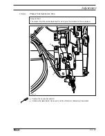
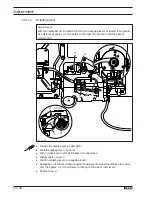
Front point of reversal of the thread catcher
Requirement
In the front point of reversal of thread catcher
3
, the rear edge of the thread catcher cut-
out should be positioned
1 mm
in front of bobbin case position stop
4
.
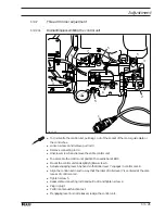
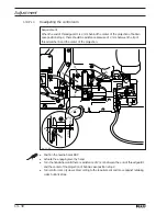
●
Press the heads of connecting rod
1
onto the ball pins on the trimmer unit and on the
control unit.
●
Loosen nuts
2
(right and left threads).
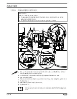
●
Position the needle bar at BDC.
●
Actuate the engaging lever by hand.
●
By turning the handwheel, position thread catcher
3
in its front point of reversal.
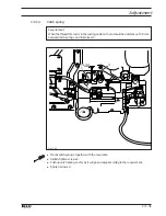
●
Turn connecting rod
1
according to the
requirement
.
●
Lock connecting rod
1
in place with nuts
2
.
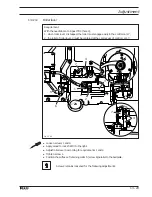
Fig. 13 - 28
2
2
1
4
3
1 mm