PESA Cougar 3 User Manual Download Page 48


C

OUGAR

3


V

IDEO 

R

OUTER


Publication 81-9059-0660-0, Rev. B 

March 2011 


Proprietary Information of PESA


5-13 


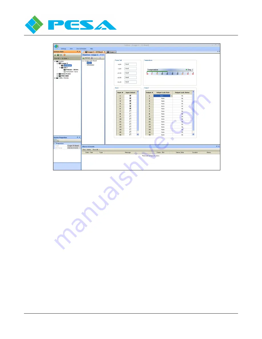
FIGURE 5-9  ROUTER CONFIGURATION TREE COMMANDS 


Power Rail - Displays the real-time Good/Bad status of each voltage rail present on the main 
router board. 


Temperature - Meter display provides a direct analog readout of current surface temperature of 
main router board. 


Input - The Input box displays current status of physical signal input ports to the router. The 
left-hand column labeled Input # lists, by port number, physical inputs available on the router. 
The right-hand column, labeled Input Detect, identifies whether a video signal is currently 
connected to the physical input. An X in the box associated with a particular input indicates 
presence of a video signal to the input port. 


Output - The Output box displays current status of video output signals from the router. The 
left-hand column labeled Output # lists, by port number, physical outputs of the router. The 
right-hand column, labeled Output Lock Status, displays the re-clocked data rate of the video 
signal at the output port. The middle column labeled Output Lock Rate, opens a pull-down 
selection box, Figure 5-10, that allows you to specify a data rate for the output signal; select 
automatic (Auto) rate selection; or Bypass the output re-clocker devices.   


Summary of Contents for Cougar 3

Page 1: ...Publication 81 9059 0660 0 Rev B www pesa com March 2011 Phone 256 726 9200 USER GUIDE 3GBPS COMPATIBLE DIGITAL VIDEO ROUTING SWITCHER...

Page 2: ...nd we look forward to a long term partnership with you and your facility SALES SERVICE AND ORDERING ASSISTANCE PESA Corporation 103 Quality Circle Suite 210 Huntsville AL 35806 USA www pesa com MAIN O...

Page 3: ...3 Router Closed Ethernet Loop Configurations 3 5 3 4 2 Integrate Cougar3 Router Into Facility Network 3 6 3 5 VIDEO CONNECTIONS 3 7 3 6 SYNC REFERENCE CONNECTIONS 3 7 3 7 POWER CONNECTIONS 3 8 CHAPTER...

Page 4: ...Window 5 9 5 7 COUGAR3 VIDEO ROUTER DEVICE PROPERTIES 5 9 5 8 SSC3 CONTROLLER DEVICE PROPERTIES DISPLAY 5 10 5 8 1 Setting SSC3 Controller Network Parameters 5 10 5 9 COUGAR3 STATUS DISPLAY 5 12 5 10...

Page 5: ...2 3 REAR PANEL CONNECTIONS COUGAR3 STAND ALONE SSC3 CONFIGURATION 2 2 FIGURE 2 4 TYPICAL INSTALLATION 3500PRO CONTROLLER 2 4 FIGURE 2 5 TYPICAL INSTALLATION PERC2000 CONTROLLER 2 4 FIGURE 2 6 TYPICAL...

Page 6: ...EL STATUS DISPLAY 5 20 FIGURE 5 18 SALVO STATUS DISPLAY 5 21 FIGURE 5 19 ACTIVE STANDBY MENU SCREEN 5 22 FIGURE 5 20 TYPICAL RIGHT CLICK MOUSE COMMANDS 5 24 FIGURE 5 21 SYSTEM PARAMETERS SCREEN 5 28 F...

Page 7: ...nel Equipping the Cougar3 with the available Small Scale System Controller SSC3 module incorporates the system controller function with the video frame creating a versatile full featured self containe...

Page 8: ...f terminating unbalanced BNCs with auto EQ conforming to SMPTE259M SMPTE292M and SMPTE424M Return Loss 15dB 1MHz to 1 5GHz 10dB 1 5GHz to 3GHz Equalization 300m auto equalization Belden 1694A or equiv...

Page 9: ...control panels Supports single bus multi bus and XY control panels using external system controller Serial 422 PRC I F 4 wire full duplex multi drop serial RS422 port capable of accepting QuStream PE...

Page 10: ...that monitors and controls operation of the fans In stand alone configuration the Cougar3 video frame is factory equipped with a small scale System Controller Power Supply Module installed in the pri...

Page 11: ...Rear panel connections used when installing the Cougar3 to an external system controller over the PRC bus interface are shown by Figure 2 2 and connections used when installing the router as a stand...

Page 12: ...al digit for the desired level setting To set the router as strobe level 1 set the switch to position 1 to set level 15 set the switch to position F etc Power Cord Connector Access Each power supply c...

Page 13: ...al installations are shown pictorially by Figure 2 4 for the 3500PRO controller and Figure 2 5 for the PERC2000 controller Figure 2 4 Typical Installation 3500PRO Controller Figure 2 5 Typical Install...

Page 14: ...of the router installation is connected to the facility network Figure 2 7 illustrates the same components in a network installation In this application every router component can be directly connect...

Page 15: ...nt in controller function For purposes of this brief introduction the basic functional difference is discussed in the following paragraphs The two modules are identified as follows Power Supply Fan Co...

Page 16: ...ipment manufacturer s suggested torque settings Fans mounted inside of this equipment provide forced air cooling Do not block airflow around these fans INSTALL VIDEO FRAME Detach front cover or local...

Page 17: ...STALL REAR SUPPORT RAILS Your Cougar3 router is shipped with a Rear Rack Rail Kit It is important that this kit be installed as part of the mounting procedure for the frame Major components included w...

Page 18: ...PRC Interface Port of the router to the female 9 pin D PRC cable Install the adapter as shown in Figure 3 2 and connect one end of the PRC hook up cable to the male end of the adapter System controll...

Page 19: ...controller communicates system commands to the router and all PNet control panels PESA s Cattrax control software application running on a host PC is the operator interface with the Cougar3 router Al...

Page 20: ...factory configured IP address values Primary System Controller 192 168 1 203 Video Frame Local Control Panel 192 168 1 205 Once the router system and host PC are communicating you may use Cattrax to...

Page 21: ...tion the values may be changed through operator menus available through Cattrax refer to Cougar3 User Guide for further information Figure 3 4 and the procedure sequence below installs Cougar3 to the...

Page 22: ...ly generated sync reference signal In many applications asynchronous switching is acceptable but in other circumstances synchronous vertical interval timed switching is used to prevent a visual glitch...

Page 23: ...wer supply module Each power supply carries its own dedicated power receptacle Input power is not bussed between modules When two power supplies are used for redundancy a separate power cord must be a...

Page 24: ...nd allow an operator to control designated functions of the router from a remote station Refer to documentation supplied with the system controller for information on writing and using configuration f...

Page 25: ...itch the three signals from NET1 to VTR1 through our router as single sources to single destinations We would have to configure an individual source named for example NET1VID for the video signal anot...

Page 26: ...a source group entry that creates a router source by the name of NET1 and define that whenever the source named NET1 is selected at a router control panel Physical input 1 to the Cougar video router...

Page 27: ...A Breakaway switch allows you to selectively choose specific sources for each switching level defined for the destination Again using devices NET1 and VTR1 from previous examples let s assume that we...

Page 28: ...reation of data key lists During control panel configuration a Status Level and Default Destination must be specified for each panel Status Level allows you to specify the switching level that the pan...

Page 29: ...ces the SOURCE DEST Number keys in source select and status mode When the Source Select key is illuminated pressing any number key selects the source group routed to currently selected destination DES...

Page 30: ...ATUS AND TALLY FUNCTIONS All active PNet panel pushbuttons are backlit for ease of viewing in low light environments In order to be active on the panel source destination and level keys must be define...

Page 31: ...button that is not backlit indicates there is no switching level defined for the button No Levels Selected Indicates panel is operating in All Levels Switch mode and any Source button you press will s...

Page 32: ...ATION Select Key on the local control panel the button will light Press the number key 1 32 corresponding to the Destination destination group you want to select When you select a destination output p...

Page 33: ...n the breakaway selection When you select a destination output ports defined through the destination group assigned to the destination number key are selected both the DEST key and the selected number...

Page 34: ...the number key configured to source group REC1 in this example IN2 the button lights Press level keys 2 and 3 a second time to de select breakaway and return the panel to AFV operation 4 10 3 PERFORMI...

Page 35: ...button on the panel to cancel the mode and return the panel to Hot Take mode The illuminated number key displays the source currently routed to the selected destination 4 11 APPLYING DESTINATION PROTE...

Page 36: ...trax you can create application specific files that define all operational aspects for the router Once created a configuration file can be stored edited or downloaded to the system controller device t...

Page 37: ...Cattrax exe file The banner shown above should be displayed on the desktop Click Next to begin installation Read the license agreement and click I Agree to continue as shown below The Choose Componen...

Page 38: ...x application If you wish to install the software in a directory or folder other than the default click Browse and navigate to the destination Click Install to continue installation During installatio...

Page 39: ...roprietary Information of PESA 5 4 Click Finish to exit the installation process During installation a shortcut icon to launch Cattrax is automatically placed on the desktop If the box next to Run Cat...

Page 40: ...discover and communicate with a Cougar3 router or any other piece of PESA equipment the proper data file must be present in the version of Cattrax used Cattrax automatically searches for PESA equipme...

Page 41: ...A network controllable devices Cattrax should immediately begin the discovery process for all devices configured for the same subnet In some installations PESA devices may reside on subnets different...

Page 42: ...ick the checkbox to remove the check If you need to add additional subnets or modify address parameters of currently available subnets use the buttons to the right of the display window as follows Add...

Page 43: ...the view mode devices may be displayed in groups by device type as shown Notice that the heading Routers appears in the menu tree with a branch to a Cougar3 router When a PESA device is connected to...

Page 44: ...Figure 5 4 Example Alarms and Events Screen 5 7 COUGAR3 VIDEO ROUTER DEVICE PROPERTIES When a Cougar3 router with small scale system controller is discovered on the network its assigned name is added...

Page 45: ...PARAMETERS The lower area of the Device Properties Display labeled IP Address displays current network parameters for the system controller The SSSC3 device does not support DHCP protocol and the fact...

Page 46: ...tatus of the Primary and Redundant controller devices as shown by Figure 5 7 If a redundant controller is present the current active or standby status of each device is indicated If no controller devi...

Page 47: ...n Cougar3 Displays real time status information for the Cougar3 router Matrix size of router in syntax of number of inputs x number of outputs OK Error status of power feed to main board Measured temp...

Page 48: ...The right hand column labeled Input Detect identifies whether a video signal is currently connected to the physical input An X in the box associated with a particular input indicates presence of a vid...

Page 49: ...vice as a Cougar I O Board I O Range Displays the numerical range of the input and output ports of the router FPGA Version Identifies the version number of firmware code loaded into the on board FPGA...

Page 50: ...nds that are specific to the router configuration file is displayed as the top item of the Menu Tree as shown by Figure 5 13 FIGURE 5 13 CONTROLLER FILE COMMANDS Refresh Refreshes currently displayed...

Page 51: ...ll box beside the Load from File command entry as a visual indication that the displayed file is not the currently active controller file 5 11 2 SSC3 INFORMATION SCREEN When the SSC3 Information entry...

Page 52: ...ained on the indicated controller module Fan Indicates current status of cooling fan on board the indicated controller module 5 12 SSC3 CONTROL MENU Commands and screens contained under the SSC3 Contr...

Page 53: ...es all the preset switches to occur simultaneously Switches can be selectively chosen by highlighting one or more destination cells and pressing the Take Selected button Clear All Clears all preset en...

Page 54: ...TR 2 on the VIDEO1 level If any cell in a switching level column is blank there is no active switch for the indicated level A scroll box on the right hand side of the screen contains a list of all sou...

Page 55: ...7 displays the current status of all PNet control panels in the router system Each entry in the spreadsheet is described below FIGURE 5 17 PANEL STATUS DISPLAY Panel ID Displays the active hardware ID...

Page 56: ...up by clicking the Fire Salvo button 5 12 5 ACTIVE STANDBY For both the Primary and Redundant SSC3 controller in the frame the Active Standby status screen Figure 5 19 displays the IP address and curr...

Page 57: ...ing from incorrect sources being switched to total shutdown of the entire system Be sure you know exactly what you want to do before you make changes to the system configuration When the SSC3 Configur...

Page 58: ...on changes It is not necessary to have an active connection between the host computer and the system controller to create and save a configuration file But in order to download a configuration upload...

Page 59: ...and incrementing the numerical value of a starting entry into fields selected by a user defined data block Copy increment always fills in all valid fields of the data grid lines within the selected bl...

Page 60: ...ented by one up to the maximum number of physical inputs or outputs defined for the level If the fill block contains additional lines after any level column reaches the maximum number any successive f...

Page 61: ...witching level columns will be incremented by one up to the maximum number of physical inputs or outputs defined for the level in the starting entry field If the fill block contains additional fields...

Page 62: ...or several fields with this function as shown Fill Right Command Fill Left Fill Left fills in the fields to the left of a selected field with the selected number s First select the fields with the num...

Page 63: ...e the chop rate enter the desired value in the Chop Rate box Any desired Chop Rate between 1 and 255 frames is supported by the SSC3 Default value of this parameter is 10 frames Sync Reference Definit...

Page 64: ...Levels box to access a blank set up screen in the Information box Deleting a Level To delete a level locate the nickname of the level you wish to delete in the Levels box and click on the name to sele...

Page 65: ...f the switching level or add notes or information as desired This field is solely for discretionary use and has no effect on the defined level characteristics 5 15 3 COMPONENTS CONFIGURATION When the...

Page 66: ...e you can select the name in this field Input and Output Offset Offset defines the numerical difference between the physical input or output number and the level input or output number for a given sou...

Page 67: ...that will appear in the switching level columns on the Matrix Status display screen Long Name This column is essentially a free text space where you may enter a name up to 32 characters in length for...

Page 68: ...ar and move the display to the empty row beneath the last source entry in the spreadsheet Click the cursor in the Name cell on the empty row and begin typing the name of the source group you wish to a...

Page 69: ...enu Tree to access the Destination Configuration Screen Figure 5 25 This screen allows you to define destination groups in the router configuration Note the Destinations Screen is in the form of a dat...

Page 70: ...ppear in the switching level columns on the Matrix Status display screen Long Name This column is essentially a free text space where you may enter a name up to 32 characters in length for the destina...

Page 71: ...to add a single destination entry use the scroll bar and move the display to the empty row beneath the last destination entry in the spreadsheet Click the cursor in the Name cell on the empty row and...

Page 72: ...mber of sources to create such as 5 This example would create sources CAM 3 to CAM 7 Set Sync Reference The Cougar3 router accepts up to two sources of external Sync Reference signals for synchronizin...

Page 73: ...ndow you assign a sync source to the destination using the pull down menu boxes Three radio buttons allow you to assign the sync source to only the Current Destination All Destinations or Selected Des...

Page 74: ...e box labeled Information on the right side contains the data entry cells used to create new or modify existing source block assignments Note the Information block has three areas Figure 5 26 Source D...

Page 75: ...ains a listing of all destinations by name with at least one blocked source If you wish to access source block configuration for a specific destination click on the destination name in the listing Fro...

Page 76: ...ields are provided for naming the salvo group In the case of the salvo configuration PESA recommends that you choose a name that is descriptive of the function of the salvo In this example the name AL...

Page 77: ...screen Figure 5 28 Data Key Lists Configuration Screen Adding a Data Key List To add a data key list click the Add button at the bottom of the Data Key Lists box A place holder name is added to the li...

Page 78: ...Enter a name for the data key list PESA recommends you assign a name that is somewhat descriptive of the function of the data key list or the type of panel it controls In this example we have used the...

Page 79: ...cell of the key row to highlight the data entry fields On the right hand side of the screen you will see three scroll lists for Sources Destinations and Levels Each Key entry in the list can be assign...

Page 80: ...ry in the SSC3 Configuration menu brings up the panels configuration screen Figure 5 30 Panels Configuration Screen Adding a Control Panel To add a PNet control panel click the Add button at the botto...

Page 81: ...me to each panel If you are adding a new panel the place holder name entered by Cattrax will initially appear in this column You may change the name to a more descriptive panel name if you wish A pane...

Page 82: ...authority to clear it by meeting one of these criteria The panel originating the lock function can unlock the destination Any panel with a higher lock priority The key difference between protect and l...

Page 83: ...ter the specific operational parameters for the panel in the box located beneath the panel as shown in the illustration below Each cell in this table uses a pull down menu to display the options avail...

Page 84: ...ation file is re loaded 5 16 1 USING ONLINE UPDATE MODE In order to use Online Update the configuration file active in Cattrax must initially be the same file as currently loaded into the SSC3 control...

Page 85: ...u make additions modifications or deletions to available configuration parameters each change you make is listed in the online update bar display area as shown in Figure 5 34 Table 5 1 Available Onlin...

Page 86: ...l permanently remove the item from the update listing You will be prompted prior to deletion of the item Undo Selecting Undo will immediately remove the item from the listing however the Undo command...

Page 87: ...ay void your warranty PC boards in this equipment contain Surface Mount Technology SMT components Special tools and skills are required to replace these components without causing damage to adjacent a...

Page 88: ......

Reviews: