Pagina 30 di 53
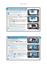
4 - INSTALLATION
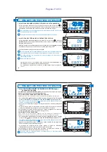
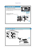
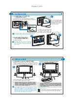
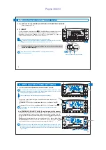
4.1) OVERALL DIMENSIONS
4.2) INSTALLATION STANDARDS
Chronothermostat installation: independent fixed
•
•
4.3) FASTENING THE WALL-MOUNTED BASE
•
Install the chronothermostat at approx. 1.5 ÷ 1.6 m.
•
Wall mounted - onto a recessed rounded box - semi-recessed
with a rectangular 3 module box.
Install the chronothermostat far from sources of heat, windows
and anything that may alter standard operation.
Fasten to the wall, to the rounded or rectangular recessed box,
via the relative paired holes “ ”.
A
To ensure the chronothermostat is fitted correctly to the wall mounted
base, the latter must not be bent due to the screws being tightened
too much to the recessed rectangular box.
A- fastening holes
B- cable duct of
the rounded or
rectangular box
C- fastening teeth
of the chrono-
thermostat
Table base available (optional)
h 1,5m
A
C
3 2 1
5
4
6 7 8 9
A
C
B
22
DAY
PROG
K
Test
Master
27,6
120
82
t1
t2
t3
0
8
10 12 14 16 18 20 22
2
4
6
.
.
.
58
EN
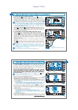
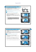
4.4) INSTRUCTIONS FOR THE INSTALLER
•
•
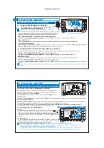
DENSE VEGETATION
trees, hedges, shrubs, etc.
radio range reduction of 10%÷25%
WOOD OR
PLASTERBOARD WALLS
radio range reduction of 10%÷30%
BRICK OR STONE WALLS
radio range reduction
of 40%÷60%
CONCRETE WALLS
radio range reduction
of 50%÷70%
METAL WALLS and/or FLOORS
radio range reduction of 65%÷90%
Chronothermostat data is sent entirely via radio.
For this reason, during installation, always take into account some
necessary precautions to avoiding limiting or, in some cases,
inhibiting radio wave range; namely:
- install the device away from furniture or metal structures that could
alter or shield the propagation of radio signals
- ensure that there are no other electric or electronic devices (TV,
microwave, etc.) within at least 1 metre from the device
- if possible, install the device in a central position. If the apartment
is made up of several floors, install the device on a middle floor.
In the absence of barriers between the chronothermostat and
control elements (valves, receiver, etc.) flow rate in "free air" is
about 120 m (see "technical specifications").
4 - INSTALLATION
Radio range decreases significantly when the components are
interposed between the obstacles. This attenuation varies in
different degrees depending on the type of material the walls or
barriers to cross are made of. The presence of noise or
electromagnetic interference sources can also reduce the
indicated radio range. Below are some examples of mitigation
related to materials, which impact on the "Free air" range declared
above.
With support from the “
” function (see paragraph 4.9) it is
test
possible to check the optimal position (the best signal
reception) in advance for chronothermostat and receiver
installation.
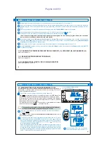
Boiler
Receiver
Chronothermostat
Installation example in a heating system with wireless chronothermostat coupled
to a receiver for wall mounted boiler control
59
EN
Summary of Contents for 1TXCRTX05
Page 52: ...Pagina 52 di 53...

