


Operation
28
DK58113 Developer Kit User Manual
2
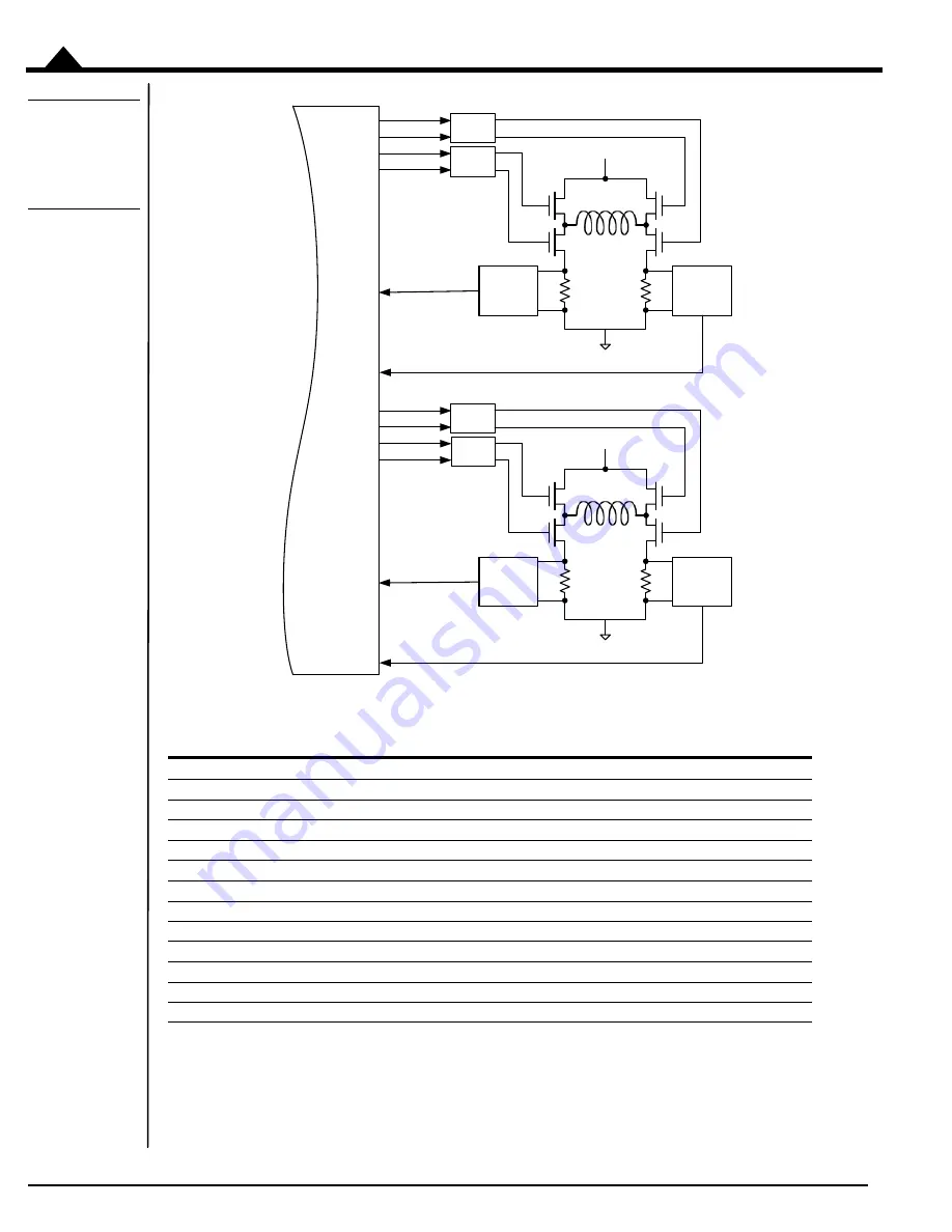
Figure 2-5:
Two-Phase
Step Motor
Bridge
Configuration
As shown in the table below eight PWM output signals and four analog feedback signals interface between the
MC58113 IC and the DK58113’s switching amplifier.
2.3.4
Amplifier-Related Settings
There are a number of MC58113 IC settings which are used to set or control various aspects of the DK58113’s
on-card switching amplifier and related current sense circuitry. If a remote amplifier (via the J12 connector) is
MC58113 signal
Description
PWMHigh1A
Digital high side drive output for motor phase A, positive coil terminal
PWMLow1A
Digital low side drive output for motor phase A, positive coil terminal
PWMHigh1B
Digital high side drive output for motor phase A, negative coil terminal
PWMLow1B
Digital low side drive output for motor phase A, negative coil terminal
PWMHigh1C
Digital high side drive output for motor phase B, positive coil terminal
PWMLow1C
Digital low side drive output for motor phase B, positive coil terminal
PWMHigh1D
Digital high side drive output for motor phase B, negative coil terminal
PWMLow1D
Digital low side drive output for motor phase B, negative coil terminal
Current1A
Analog input containing the current flow through the positive leg of phase A bridge
Current1B
Analog input containing the current flow through the negative leg of phase A bridge
Current1C
Analog input containing the current flow through the positive leg of phase B bridge
Current1D
Analog input containing the current flow through the negative leg of phase B bridge
PWMLow1B
PWMHigh1B
PWMHigh1A
PWMLow1A
Current1A
Current1B
GND
HV
Analog
Conditioning
Analog
Conditioning
Phase A
Phase B
MC58113
or
MC54113
Current1C
Current1D
GND
HV
Analog
Conditioning
Analog
Conditioning
PWMLow1D
PWMHigh1D
PWMHigh1C
PWMLow1C
+
–
+
–
Pre-
driver
Pre-
driver
Pre-
driver
Pre-
driver


