26
.9.20
1
3
22
AS-i 3.0 EtherNet/IP+Modbus TCP Gateway
Installation
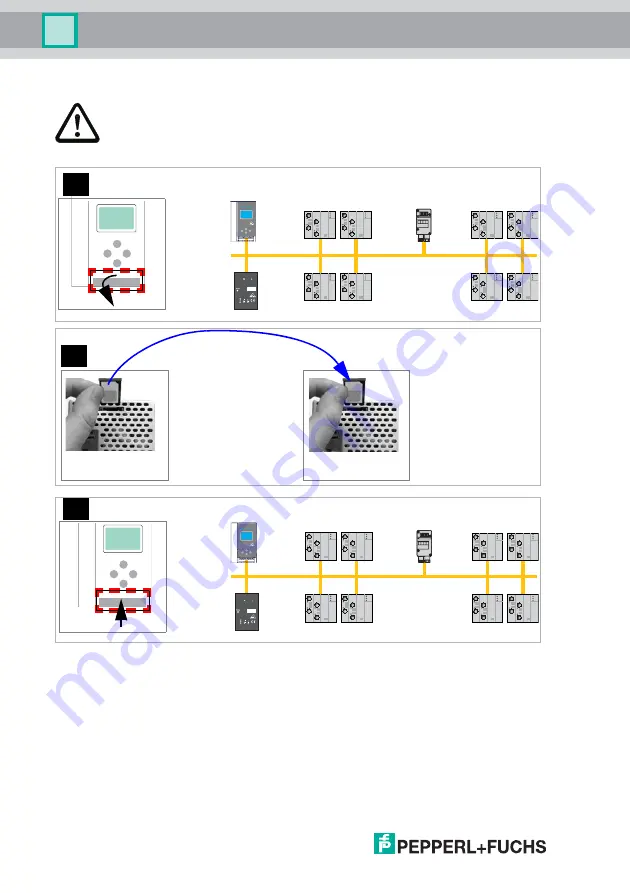
6.7.3
Replacing the chip card
Always turn off power before inserting or removing the card!
[1]
[2]
old
new
[3]
Page 1: ...AS I 3 0 ETHERNET IP MODBUS TCP GATEWAY FACTORY AUTOMATION MANUAL...
Page 2: ...ery for Products and Services of the Electrical Industry published by the Central Association of the Electrical Industry Zentralverband Elektrotechnik und Elektroindustrie ZVEI e V in its most recent...
Page 3: ...tics interface 11 4 3 AS i specification 3 0 11 5 Specifications 12 5 1 Technical data 12 6 Installation 13 6 1 Dimensions 13 6 2 Connections 13 6 3 Installing in the control cabinet 14 6 4 Removing 1...
Page 4: ...rs and operating elements 30 7 8 1 LED indicators master 30 7 8 2 Buttons 31 8 Operation in advanced display mode 32 9 Advanced Diagnostics for AS i Masters 33 9 1 List of corrupted AS i Slaves LCS 33...
Page 5: ...e 7 3 or 7 4 75 11 3 2 16 bit input data of AS i slaves according to slave profile 7 3 or 7 4 75 11 4 AS i circuit 2 data 76 11 4 1 Process data and actual configuration data 76 11 4 2 Permanent confi...
Page 6: ...ontrol Tools 88 15 Appendix Examples 91 15 1 Commissioning with RSLogix5000 V20 or higher 91 15 2 The first commissioning with CompactLogix 101 15 2 1 Working with sample files 105 16 Codes indicated...
Page 7: ...ptions and any repairs increases the effectiveness and efficiency of your plant Keep this manual at hand for subsequent operations on the device After opening the packaging please check the integrity...
Page 8: ...formity This product was developed and manufactured under observance of the applica ble European standards and guidelines The product manufacturer Pepperl Fuchs GmbH D 68307 Mannheim has a certified q...
Page 9: ...med Connecting the equipment and conducting any maintenance work under power must exclusively be performed by appropriately qualified personnel In case a failure cannot be eliminated the device must b...
Page 10: ...zed with integrated data coupling coils and adjustable self resetting fuses for safe use also of powerful 24V power supplies The gateways VBG ENX K20 D and VBG ENX K20 DMD need to add in Power24V oper...
Page 11: ...isplay AS i Power24V capable Interfaces for virtually every bus system and Ethernet solution 4 3 AS i specification 3 0 The AS i 3 0 devices already fulfil the AS i specification 3 0 The previous spec...
Page 12: ...AS i 3 0 EtherNet IP Modbus TCP Gateway Specifications 5 Specifications 5 1 Technical data The technical data are placed in the data sheet Please view the current version on the web page http www pepp...
Page 13: ...g Cover the top of the gateway when doing any drilling work above the unit No particles especially metal chips should be allowed to enter the housing since this could cause a short circuit Information...
Page 14: ...IN EN 50 022 To install place the unit on the upper edge of the DIN rail and then snap in the lower edge 6 4 Removing To remove press the holding clamps 2 down using a screwdriver 1 press the unit fir...
Page 15: ...TCP menu structure see additional page OK ESC classical display LCD 1 12A UNKNOWN SLAVE LCD ETHERNET QUICK SETUP SLAVE ADR TOOL advanced display mode SLAVE TEST TOOL The device handels multiple proto...
Page 16: ...C OK ACTUAL VALUES 192 168 000 254 NET MASK 255 255 255 0 GATEWAY 0 0 0 0 ETHERNET TCP IP MODBUS ACTUAL VALUES CONFIGURATION IP ADDRESS OK ESC ETHERNET TCP IP MODBUS ACTUAL VALUES CONFIGURATION OK CON...
Page 17: ...erNet IP ETHERNET TCP IP MODBUS OK ESC WATCHDOG TIME 200 in 10ms steps 000 disable OK ETHERNET QUICK SETUP SLAVE ADR TOOL SLAVE TEST TOOL MODBUS TCP ETHERNET IP X MODBUS TCP X ETHERNET IP ETHERNET IP...
Page 18: ...X MAILBOX MODE 36 BYTE OK 36 Byte Compatibility mode for older devices MAILBOX MODE OK TCP IP OBJECT ETHERNET OBJECT IF STATUS IF CAPABILITY IF CONTROL USE DHCP If you do not have DHCP client access...
Page 19: ...ecting AS i Slaves Slave 1 AS i Slave 5 AS i LCD 0 5s 0 5s Slave 1 AS i Slave 5 AS i AS i prj mode config error prg enable AS i active U AS i net power AS i prj mode config error prg enable AS i activ...
Page 20: ...setup config error LCD CONFIGURATION OK ETHERNET QUICK SETUP SETUP IO PARAM TEST WARNING OUTPUTS MAY BE RESET STORE AS I CONFIGURATION STORE RUN STORE AS I CONFIGURATION OK LCD 1 5 LCD HOST ERROR NO C...
Page 21: ...config error prg enable AS i active U AS i net power 1 24 MISSING SLAVE MISSING SLAVE 2s 2s LCD LCD AS i Master Slave 1 AS i Slave 5 AS i Slave 24 AS i AS Interface 24 set Slave 1 AS i Slave 5 AS i Sl...
Page 22: ...26 9 2013 22 AS i 3 0 EtherNet IP Modbus TCP Gateway Installation 6 7 3 Replacing the chip card Always turn off power before inserting or removing the card 1 2 old new 3...
Page 23: ...ert Device card data not equal Factory configuartion changed Fehlermeldung Error message Ger te Chipdaten gleich Device data card data equal Keine Meldung No message Keine Aktion erforderlich No actio...
Page 24: ...indicators and operating elements 7 1 1 VBG ENX K20 D VBG ENX K20 DMD VBG ENX K20 DMD EV Legend 1 LEDs 2 Ethernet interface 3 LC display 4 Buttons 5 Terminals Supply voltage and AS i circuit 6 Chip ca...
Page 25: ...nly by electrical technicians Information A listing of the individual devices and their features can be found in section Product information Information The cable indicated by grey must not have slave...
Page 26: ...0 D ASI PWR max 8A ASI ASI ASI ASI NC NC ASI PWR M4 5 mm max Function ground Terminal Signal Description AS i Connection to AS i Circuit ASI PWR Supply voltage for AS i Circuit max 8 A FE Function gro...
Page 27: ...l Signal Description ASI 1 Connection to AS i circuit 1 ASI 2 Connection to AS i circuit 2 ASI 1 PWR Supply voltage for AS i circuit 1 max 8 A ASI 2 PWR Supply voltage for AS i circuit 2 max 8 A FE Fu...
Page 28: ...ower24V capable and can be operated directly on a 24V PELV power supply FE Function ground ASI1 ASI1 ASI PWR max 4A 24V 0V ASI2 ASI1 ASI1 ASI2 ASI PWR 24V 0V M4 5 mm max Function ground Information AS...
Page 29: ...terface in conjunction with AS i Control Tools software is used for communication between the PC and the unit 7 6 1 Diagnostics port RS 232 The service and diagnostics interface is configured as a min...
Page 30: ...e the actual configuration data does not match the nominal configuration data or the master is in the startup proc ess This LED flashes if a peripheral fault has been detected for at least one AS i sl...
Page 31: ...For additional information see section Operation in advanced display mode Mode Switching between configuration mode and protected operating mode and saving the current AS i configuration as the nomin...
Page 32: ...AS i 3 0 EtherNet IP Modbus TCP Gateway Operation in advanced display mode 8 Operation in advanced display mode Information You will find a description of the display menu in the separate document Di...
Page 33: ...ent AS i power failures are listed in the LCS at the position of AS i slave with address 0 9 2 Protocol analysis Counters for corrupted data telegrams The AS i master with advanced diagnostics provide...
Page 34: ...the error message is sent to the host but AS i is still running Like the advanced diagnostics the parameterization offline phase on configura tion error is also supported by AS i Control Tools Comman...
Page 35: ...oises is indicated on the master s display as well as in AS i Control Tools 9 4 4 Over voltage Detector Over voltages are present if the conductors of an AS i network that normally are routed electric...
Page 36: ...re com plex applications the C programmable Gateways make the work of the PLC easi er for example by pre processing special functions 9 5 2 Interchangeable memory card Main menu SETUP CHIPCARD AS I CH...
Page 37: ...ay both the maximum current and the current actually present in the respective AS i circuit Heavy consumers or a strong overload in an AS i circuit are then easy to detect Plus you can set the maximum...
Page 38: ...ngful assist ance towards rapid troubleshooting The fuse resets itself periodically to check if the error is solved The measured current value is available as diagnostic information at the field on th...
Page 39: ...in reach 9 5 8 Transitionless operating mode changes Main menu SETUP MODE CHANGE These devices are able to change the operating mode from projecting mode to the protected operating mode without having...
Page 40: ...ve I O data Advanced diagnostics Short command interface Long command interface Safety Control Status external Class code Object name Number of instances 0x01 Identity 1 0x02 Message router 1 0x04 Ass...
Page 41: ...dor 5 2 get device type 12 3 get product code e g 2386 double master e g 2385 single master 4 get revision 1 1 5 get status see overwiev listed below 6 get serial number unique number 32 bit 7 get pro...
Page 42: ...bute ID Access Rule Name Value 1 0x01 get network topo logy 0 linear 1 ring 2 0x02 get network status 0 normal 1 ring fault 10 0x0E get active supervi sor address byte 0 3 ip adress byte 4 9 mac adres...
Page 43: ...set dscp low dscp after rfc 3168 for cip class 0 1 low default 31 8 0x08 get set dscp explicit dscp after rfc 3168 for cip class 3 ucmm default 27 Tab 10 7 Service Code Class Instance Service Name 14...
Page 44: ...P interface Mapping of the SDCP and 802 1D priorities to the queues is as follows Switch queue DSCP 802 1D priority 4 highest priority 59 7 3 46 DSCP Urgent DSCP Scheduled DSCP High 4 5 6 2 24 DSCP Lo...
Page 45: ...Long command interface 16 bit data of slaves 29 31 from circuit 1 or from both circuits in the follow ing format 16 bit data of slaves 29 31 byte data item attribute ID 3 n Slave 31 ch1 high byte n 1...
Page 46: ...read while instances 136 0x88 171 0xAB can be read and written n 20 Slave 29 ch3 high byte n 21 Slave 29 ch3 low byte n 22 Slave 29 ch4 high byte n 23 Slave 29 ch4 low byte 16 bit data of slaves 29 3...
Page 47: ...29 31 113 0x71 149 0x95 68 short 114 0x72 150 0x96 94 long 115 0x73 151 0x97 80 AS i circuit 1 2 analog slaves 29 31 116 0x74 152 0x98 92 short 117 0x75 153 0x99 118 long 118 0x76 154 0x9A 32 AS i cir...
Page 48: ...OL 109 0x6D get set Change_Slave_Adress UINT 110 0x6E get set Lock push buttons BOOL Tab 10 12 EC flags 16 bit 215 214 213 212 211 210 29 28 27 26 25 24 23 22 21 20 DA NSE OV EF Pok OR APF NA CA AAv A...
Page 49: ...ed S0 LDS 0 There is an AS i slave with address 0 Cok config_ok Configuration error 0 no error 1 error Hi flags 8 bit 22 21 20 AAe OL DX Tab 10 14 AAe Auto_Address_Enable OL Off line DX Data_Exchange_...
Page 50: ...rface Store actual parameter store actual configuration lock push buttons True proceed the action Change slave address 16 bit Byte 27 26 25 24 23 22 21 20 0 B source address 1 B target address Tab 10...
Page 51: ...1 empty circuit 2 98 0x62 slave 1B circuit 2 128 0x80 slave 31B circuit 2 Tab 10 17 attribute ID access rule name devicenet data type remark 100 0x64 get actual configuration UINT 101 0x65 get set per...
Page 52: ...ata type default data value 100 get input data image single and A slaves ARRAY 16 of USINT 101 get input data image B slaves ARRAY 16 of USINT 102 get set output data image single and A slaves ARRAY 1...
Page 53: ...9 slave 18 18A slave 19 19A 10 slave 20 20A slave 21 21A 11 slave 22 22A slave 23 23A 12 slave 24 24A slave 25 25A 13 slave 26 26A slave 27 27A 14 slave 28 28A slave 29 29A 15 slave 30 30A slave 31 3...
Page 54: ...data area There fore accessing 16 bit data is as easy as accessing digital data Flags Input data Output data F0 ConfigError Off line F1 APF LOS master bit F2 PeripheryFault ConfigurationMode F3 Confi...
Page 55: ...Slave error counter attribute ID access rule name devicenet data type default data value 100 0x64 Get Set LOS List of offline slaves ULINT 101 0x65 Get error counter A ARRAY 32 of USINT 102 0x66 Get...
Page 56: ...acc the command interface commands see the separat manu al AS i 3 0 Command Interface attribute ID access rule name devicenet data type default data value 100 0x64 get set content ARRAY 12 of USINT co...
Page 57: ...8 7 130 0x82 get slave 31 ARRAY 8 of USINT safety status release circuit 1 0 safety status release circuit 2 1 2 6 safety status release circuit 8 7 131 0x83 get set safety control slave 1 USINT 161...
Page 58: ...manent lighting 0116 green flashing 0216 yellow permanent lighting 0316 yellow flashing 0416 red permanent lighting 0516 red flashing 0616 grey or off 0716 reserved Bit 6 status or color 0 no device f...
Page 59: ...slave 7 7A 4 49 66 slave 8 8A slave 9 9A slave 10 10A slave 11 11A 5 65 80 slave 12 12A slave 13 13A slave 14 14A slave 15 15A 6 81 96 slave 16 16A slave 17 17A slave 18 18A slave 19 19A 7 97 112 sla...
Page 60: ...21 336 slave 8 8A slave 9 9A slave 10 10A slave 11 11A 22 337 352 slave 12 12A slave 13 13A slave 14 14A slave 15 15A 23 353 368 slave 16 16A slave 17 17A slave 18 18A slave 19 19A 24 369 384 slave 20...
Page 61: ...49 66 slave 8 8A slave 9 9A slave 10 10A slave 11 11A 5 65 80 slave 12 12A slave 13 13A slave 14 14A slave 15 15A 6 81 96 slave 16 16A slave 17 17A slave 18 18A slave 19 19A 7 97 112 slave 20 20A sla...
Page 62: ...321 336 slave 8 8A slave 9 9A slave 10 10A slave 11 11A 22 337 352 slave 12 12A slave 13 13A slave 14 14A slave 15 15A 23 353 368 slave 16 16A slave 17 17A slave 18 18A slave 19 19A 24 369 384 slave 2...
Page 63: ...nicant bit Reference 1 Flag bit bit value write read F1 1 8000h Data_Exchange_Active Config_OK F2 2 4000h Off Line LDS 0 F3 3 2000h Auto_Address_Enable Auto_Address_Assign F4 4 1000h Configuration Mod...
Page 64: ...with address zero exists Auto_Address_Assign Automatic programming is allowed Auto_Address_Available Automatic programming is possible 0 Auto address is possible 1 Auto address is not possible Config...
Page 65: ...alue write read 1 8000h ODI slave 0 D0 IDI slave 0 D0 2 4000h ODI slave 0 D1 IDI slave 0 D1 3 2000h ODI slave 0 D2 IDI slave 0 D2 4 1000h ODI slave 0 D3 IDI slave 0 D3 5 800h ODI slave 1 D0 IDI slave...
Page 66: ...lse disabled 2086 r return value of most recently called Execution Control function 0 success 1 failure 2 slave with 1st address not detected 3 slave with zero address detected 4 slave with 2nd addres...
Page 67: ...revision number 63494 r ASCII header size in words ASCII header is largely printable and starts at 64512 63495 r internal diagnostic not used 63496 r reservation time remaining not used 63497 r watch...
Page 68: ...25 Bit value execution control flags 1h Config_OK 2h LDS 0 4 Auto_Address_Assign 8h Auto_Address_Available 10h Configuration_Active 20h Normal_Operation_Active 40h APF not APO 80h Offline_Ready 100h P...
Page 69: ...t APO An AS i power fail occured Offline_Ready The off line phase is active Periphery_OK Periphery is OK 0 Periphery is not OK 1 Periphery is OK Earth Fault AS i earth fault detection 0 no earth fault...
Page 70: ...uto address is disabled 1 Auto address is enabled 4x reference 4145 4208 Bit mask data 000Fh I O configuration 00F0h ID code 0F00h extended ID 1 code F000h extended ID 2 code Tab 11 45 LAS LOS LPS LCS...
Page 71: ...s external monitor data for read access 4x reference access data read access bit value 215 214 213 212 211 210 29 28 27 26 25 24 23 22 21 20 bit 1 2 3 4 5 6 7 8 9 10 11 12 13 14 15 16 5641 r slave 1 O...
Page 72: ...s data write access bit value 215 214 213 212 211 210 29 28 27 26 25 24 23 22 21 20 bit 1 2 3 4 5 6 7 8 9 10 11 12 13 14 15 16 5889 r w reserved Slave 1 2 Y2 Slave 1 2 Y1 Slave 1 1 Y2 Slave 1 1 Y1 589...
Page 73: ...4385 4400 r w permanent parameter PP 4401 4464 r w permanent configuration data PCD 4465 4468 r w list of projected slaves LPS Tab 11 50 AS i circuit 1 enhanced diagnostic 4x reference access data 46...
Page 74: ...address Tab 11 52 Set_Operation_Mode A zero in the 4x reference 4865 activates the pro tected mode All other values switch on the configura tion mode Change_Slave_Address This function will be execute...
Page 75: ...nd to 0B 31B AS i circuit 1 16 bit output data of AS i slaves according to slave profile 7 3 or 7 4 data 4x reference word 215 214 213 212 211 210 29 28 27 26 25 24 23 22 21 20 5125 1 slave at address...
Page 76: ...g the PI 8241 8304 r conguration data image CDI 8305 8308 r list of activated slaves LAS 8309 8312 r list of detected slaves LDS 8313 8316 r list of periphery faults LPF 8321 r ec flags 8322 r w hi fl...
Page 77: ...ual_Configuration 5 Execute_Command 6 Send_Parameter 8961 r function result 0 success 32769 failure 32770 slave with 1st addr not detected 32771 slave with zero addr detected 32772 slave with 2nd addr...
Page 78: ...default value on power cycle If zero is written to the address 61441 the watchdog is disabled The reference 2087 holds the default value for the watchdog timeout This value is set in the register 6144...
Page 79: ...ata item is addressed as item number zero For example The coil known as coil 1 in a programmable controller is addressed as coil 0000 in the data address field of a Modbus message Coil 127 decimal is...
Page 80: ...ksum fields are not needed because the TCP IP and link layer eg Ethernet instad are used to verfiy accurate delivery of the packet request 00 00 00 00 00 06 09 03 00 04 00 01 response 00 00 00 00 00 0...
Page 81: ...ine the size of the various data regions available on the slave All exceptions are signaled by adding 128 to the function code of the request and following this byte by a single reason byte for exampl...
Page 82: ...complex request such as that the implied length is incorrect It specifically does NOT mean that a data item submitted for storage in a register has a value outside the expectation of the application p...
Page 83: ...hernet IP Modbus TCP 26 9 2013 83 0B GATEWAY TARGET DEVICE FAILED TO RESPOND Specialized use in conjunction with Modbus Plus gateways indicates that no response was obtained from the target device Usu...
Page 84: ...000 This chapter explains the data transfer of AS i 3 0 EtherNet IP Gateways using CIP Messages in RSLogix5000 13 1 MSG instruction and Message Type Tag Include a MSG instruction Create a new MESSAGE...
Page 85: ...AS i 3 0 EtherNet IP Modbus TCP Gateway Data Transfer using CIP Messages in RSLogix5000 26 9 2013 85 Select the Communication tab Browse to the AS i Ethernet IP module Check the Connected check box...
Page 86: ...2 Example 1 read LAS Select the Configuration tab in the Message Configuration window Select Message Type CIP generic Service Type Get attribute single Map For Class 64 For Instance 1 for AS i circuit...
Page 87: ...Get attribute single Map For Class 66 For Instance 1 for AS i circuit 1 For Attribute 6E 16 bit input data slave 7 As Destination create a new tag or select an existing tag to hold the incom ing data...
Page 88: ...2 Start AS i Control Tools 3 Select Master New 4 Choose RS232 diagnostic interface as the protocol 5 Select the appropriate settings for example serial interface COM 2 station address auto 6 Select M...
Page 89: ...e to open the dialog window slave configuration This window enables the user to edit a slave address and to set AS i param eters or AS i configuration data Additionally inputs and outputs can be teste...
Page 90: ...AS i master as configuration data Furthermore an AS i Address Assistant is available allowing to perform an ad dress change of a new AS i slave to the desired address as soon as it is connect ed to th...
Page 91: ...Appendix Examples 15 1 Commissioning with RSLogix5000 V20 or higher This document describes how to install and use an EDS file and an Add On In struction for AS i Ethernet IP Gateways in RSLogix5000 V...
Page 92: ...26 9 2013 92 AS i 3 0 EtherNet IP Modbus TCP Gateway Appendix Examples 2 Select Register an EDS file s 3 Select your EDS file...
Page 93: ...AS i 3 0 EtherNet IP Modbus TCP Gateway Appendix Examples 26 9 2013 93 4 Select Next until the installation is completed 5 Create a new Module in the RSLogix I O Configuration...
Page 94: ...2013 94 AS i 3 0 EtherNet IP Modbus TCP Gateway Appendix Examples 6 Select the Bihl Wiedemann GmbH AS i Gateway 7 Assign Name and IP Address and select Change to change the kind of data being transfe...
Page 95: ...data abbreviation meaning I O input and output data I only input data C1 2 A B slaves circuit 1 and 2 A and B AS i slaves C1 2 analog circuit 1 and 2 analog slaves 29 31 C1 2 slaves 10 31 analog circ...
Page 96: ...26 9 2013 96 AS i 3 0 EtherNet IP Modbus TCP Gateway Appendix Examples 9 The AS i Gateway data can now be found in the Controller Tags...
Page 97: ...ed data Free AOI examples are available AOI COP_ASi L5X copies digital data A B slaves circuit 1 und 2 three ana log slaves and the command interface AOI COP_ASi_Safety L5X copies additionally Safety...
Page 98: ...26 9 2013 98 AS i 3 0 EtherNet IP Modbus TCP Gateway Appendix Examples 11 Select the file AOI COP_ASi L5X as an example 12 Confirm the Import Configuration...
Page 99: ...3 99 13 The Add On Instruction COP_ASi and the User Defined Data Types ASI_GW_CI and ASI_GW_STRUCTURE will be created Open the AOIs Parameters and Local Tags and adapt the size of the parameters raw_i...
Page 100: ...2013 100 AS i 3 0 EtherNet IP Modbus TCP Gateway Appendix Examples 14 Open the AOIs Logic and adapt the length of the actually configured data See comments in the routine 15 Call the AOI in your prog...
Page 101: ...y data can now be found in data structures 15 2 The first commissioning with CompactLogix This chapter shows exemplarily the start up of the AS i 3 0 EtherNet IP Gateways with the software RSLogix 500...
Page 102: ...Gateway Appendix Examples Now select your controller register its name and confirm with OK Click in the tree view control window with the right mouse button on your con troller Click in the PopUp win...
Page 103: ...ata 32 bytes for digital data A B slaves 24 bytes for analog data slave address 29 31 Assembly Instances A so called Assembly Object specifies the structure of objects for the data communica tion The...
Page 104: ...lease click on the Finish button Now you can begin programming For the first downloading of the software the transmission path must be indi cated Select for this purpose from the menu Communications t...
Page 105: ...ption of the controller tags where you can find the tag Mailbox1 Here you can edit the command interface instructions You can find an appropri ate description in the Mbx0Main routine in the Mailbox Fu...
Page 106: ...hort time AS i power failure occurred 40 The AS i master is in offline phase 41 The AS i master is in detection phase 42 The AS i master is in activation phase 43 The AS i master starts the normal ope...
Page 107: ...ave address Target address is already used 92 Error while changing slave address New address could not be set 93 Error while changing slave address New address could only be stored volatile in the sla...
Page 108: ...t configuration of the slave De pending on the mode protected mode or configuration mode and on the current configuration the detected slave will be activated After each data exchange with all AS i sl...
Page 109: ...re activated Also see configuration mode This mode is intended for normal operation since all AS i protective measures are activated ID code The ID code is set by the slave manufacturer and cannot be...
Page 110: ...f the connected slaves do not match A configuration error could be due to the follow ing Missing slave A slave entered in the LPS is not available Wrong type of slave The slave profile of the connecte...
Page 111: ...the actual configuration a configuration error exists Permanent parameter The parameters saved in the master and sent to the slave after startup of the master during the activation phase Configuration...
Page 112: ...112 AS i 3 0 EtherNet IP Modbus TCP Gateway Glossary AS i 2 0 slaves do not have extended ID1 and ID2 codes A 2 1 or 3 0 AS inter face master enters in this case an F for each of the extended ID1 and...
Page 113: ...i 3 0 EtherNet IP Modbus TCP Gateway Reference List 26 9 2013 113 18 Reference List 18 1 Manual AS i 3 0 Command Interface This Manual contains a detailed description of the AS i 3 0 Command Interfac...
Page 114: ......