2
01
7-
11
22
Operation and Communication
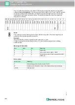
You can define the structure and content of the response telegram using the configuration
software
Vision Configurator
. This may include position data in an X- and Y-direction as well
as speed and diagnostic data. Make sure that the required settings have been configured,
transmitted to the reader, and stored there. The factory default structure of the response
telegram is as follows:
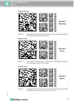
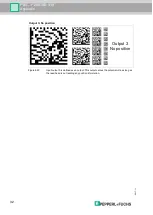
Meaning of status bits:
Error codes:
Bit 25 24 23 22 21 20 19 18 17 16 15 14 13 12 11 10 9 8 7 6 5 4
3
2
1
Data
XP21
XP20
XP19
XP18
XP17
XP16
XP15
XP14
XP13
XP12
XP11
XP10
XP9
XP8
XP7
XP6
XP5
XP4
XP3
XP2
XP1
XP0
Out
W
rn
Err
MSB
LSB
Status bits
Note!
The number of position bits required in the X-direction depends on the track length of your
system and the required position resolution.
Example:
max. track length = 300 m, required position resolution = 1 mm.
19 bits are enough to display the X position. You can therefore assign 6 bits to display
additional data.
Out
Wrn
Err
Meaning
x
1
x
Reserved
x
x
1
Error, error code in XP0 ... XP21
1
x
x
No position codes in the read window (XP0 ...
XP21=0)
Error code
Meaning
1
Reader aligned incorrectly (rotated 180
°
)
2
Position error: Position codes in the read window are not unique
>1000
Internal fault


