2
019-
03
10
M-LB-(Ex-)2000-System – Surge Protection Barriers
Product Specifications
2.4
Surge Protection Barrier
The device limits induced transients of different causes, e. g. lightning or switching operations.
The limitation is achieved by diverting the current to earth and limiting the signal loop voltage
during the duration of the overvoltage pulse.
The devices are distinguished:
•
By their working voltage
•
By their topology, see chapter 2.2
•
By operating location and area of application
•
Devices with green marking and equipment protection level Gc
for connection of non-intrinsically safe circuits
•
Devices with blue marking and equipment protection level Gb
for connection of intrinsically safe circuits
The device is mounted on a 35 mm x 7.5 mm DIN mounting rail according to EN 60715.
The DIN mounting rail is used to attach the device in the switch cabinet and is responsible
for grounding the surge protection barriers. The DIN rail mounting ensures a grounding
connection with the lowest possible resistance of the device.
Assembly
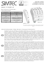
Figure 2.6
Device assembly
1
Surge protection barrier M-LB-21** with screw terminals and equipment protection
level Gc for the connection of non-intrinsically safe circuits
2
Surge protection barrier M-LB-21**.SP with spring terminals and equipment protection
level Gc for the connection of non-intrinsically safe circuits
3
Surge protection barrier M-LB-Ex-21** with screw terminals and equipment protection
level Gb for the connection of intrinsically safe circuits
4
Surge protection barrier M-LB-Ex-21**.SP with spring terminals and equipment
protection level Gb for the connection of intrinsically safe circuits
1
2
3
4
5
6
1
2
3
6
5
4
1
2
3
4
5
6
1
2
3
6
5
4
1
2
3
4


