SMART I/O User’s Manual
October 01, 1996
©1996 PEP Modular Computers GmbH
Page 6- 24
Chapter 6 Communications Modules
6.2.7.5 Compare Register
This 24-bit register indicates the comparison value and is cleared after a
power-on reset.
6.2.7.6 Identification Register
The identification register is read only and fixed at a value of $81.
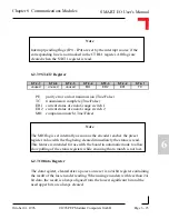
6.2.7.7 Status Register
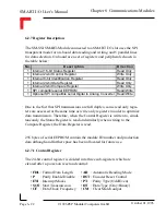
The 16-bit status register is divided into two sub-registers which are partly
cleared after a power-on reset and show:
•
IP
: Interrupt Pending flags
•
DF
: Data Flow
•
PE
: Parity Error
•
ER1
: End-of-Range 1
•
TC
: Transmission Complete
•
ER2
: End-of-Range 2
•
OL
: Open Line
•
MH
: Match
IP, PE, TC, OL, DF and MH flags are cleared after a reset. ER1 and ER2
represent the current hardware condition
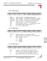
6.2.7.8 STAT1 Register
IP0-PE
interrupt pending on parity error
IP1-TC
interrupt pending on transmission complete
IP2-ER1
interrupt pending on end-of-range switch 1
IP3-ER2
interrupt pending on end-of-range switch 2
IP4-MH
interrupt pending on comparison match
DF
SSI data flow (True/False)
OL
open line (True/False)
S T 1 - 7
S T 1 - 6
S T 1 - 5
S T 1 - 4
S T 1 - 3
S T 1 - 2
S T 1 - 1
OL
unused
DF
IP4-MH
IP3-ER2
IP2-ER1
IP1-TC

