SMART I/O User’s Manual
©1996 PEP Modular Computers GmbH
March 12, 1996
Page 5 - 25
5
Chapter 5 Analog Modules
5.1.9 ISaGRAF Programming
5.1.9.1 The ISaGRAF Board Parameters
Information on board parameters may be found in the PEP online help and
ISaGRAF online help or user’s manual.
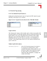
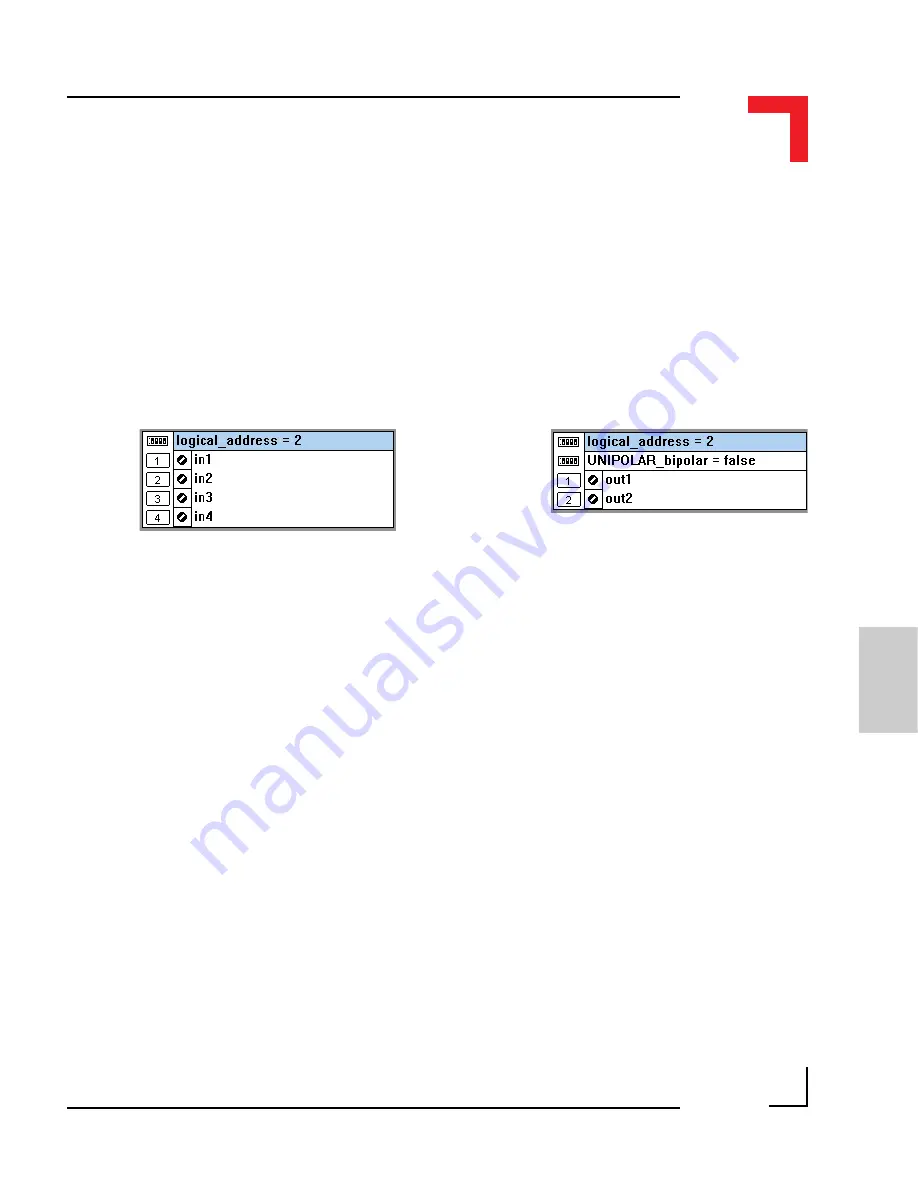
Figure 5.1.9.1.1 Typical Screen Sections for the SM-DAD1 Module
Logical Address
The 4 inputs and 2 outputs of this module may be clearly seen together with
the logical address at which this particular board is residing. Remember, this
logical address is the same as the physical slot position! In the example
shown here, the board being addressed is in slot 2 i.e. the second of the
SMART-BASE slots. Up to 11 slots are catered for in the SMART I/O
concept; 3 on the SMART-BASE and 2 for each connected SMART-EXT
(up to a total of 4).
Module Specific Information
UNIPOLAR_bipolar
:
Like all I/O board parameters, the default is
set in upper-case lettering. Here, in this
example both outputs of the module are set to
function in bipolar mode. Hardware jumpers
J4 and J5 must be set accordingly as it is
impossible under ISaGRAF to configure the
outputs individually.

