28
3.INSTALLATION
3.5.5
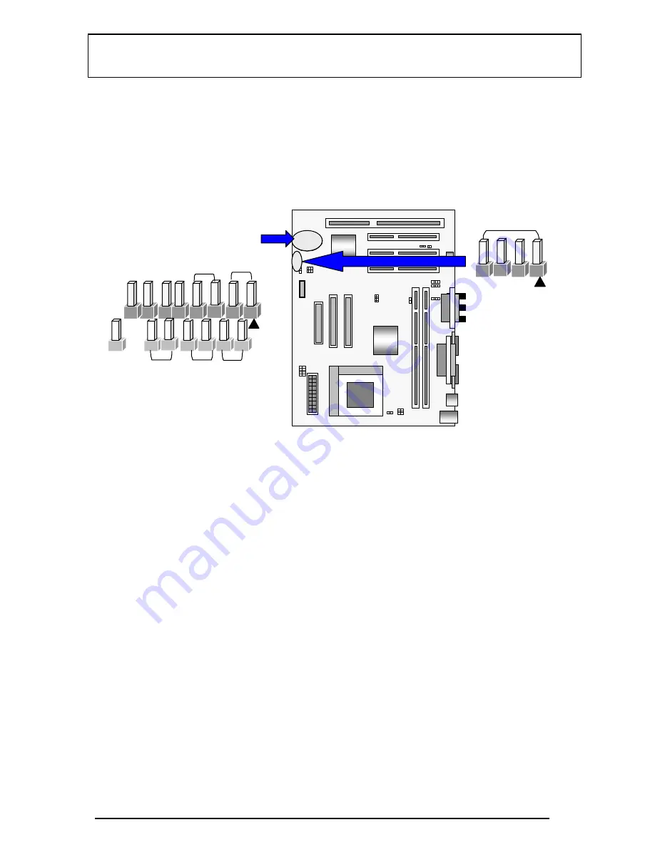
Front Panel connectors
Front Panel includes headers for the following six I/O connectors:
Power Switch, Power LED, Speaker, Reset, Sleep and HDD LED.
Reset Switch Connector (J22, 2-pin)
This connector supports the front panel case-mounted reset button. It is advised
that the reset switch be used for rebooting the system in order to extend the life
of the system’s power supply.
HDD ( IDE ) LED Connector (J22, 4-pin)
The IN530 supports one straight 4-pin header for connecting to front Panel Hard
Disk activity LED indicator.
Sleep Switch (J22, 2-pin)
When the APM (Advanced Power Management) feature is enabled in the system
BIOS and the operating system’s APM driver is loaded, the system can enter the
sleep (standby) mode in one of the following ways:
♦
Optional front panel sleep/resume button
♦
Prolonged system inactivity using the BIOS inactivity timer feature
(Section 4.5)
The 2-pin header supports a front panel sleep/resume switch, which must be a
Reset
HDDLED
Sleep
Pwr
Yel/Gre
SPEAKER
Summary of Contents for IN530
Page 1: ...1 Advanced Pentium Motherboard IN530 USER S MANUAL...
Page 5: ...5 EASY INSTALLATION...
Page 10: ...10 2 FEATURES 2 2 2 F F FE E EA A AT T TU U UR R RE E ES S S Photo Of The Motherboard...
Page 19: ...19 3 INSTALLATION Host Freq JP5 JP6 JP7 JP8 66 75 83 90 95 100...
Page 23: ...23 3 INSTALLATION rock the module forward and backward while slowly lifting it upward...
Page 37: ...37 3 INSTALLATION...


