11
SHURflo Operating Instructions, Performance,
Specifications and Parts Manual
Viton Models GMSV2A, GMSV4A, GMSV6C, GMSV2A3T, GMSV2A33T,
GMSV4A5T, GMSV4A53T, GMSV6C7T and GMSV6C73T
Teflon
®
Models GMST2A, GMST4A, GMST6C, GMST2A3T, GMST2A33T,
GMST4A5T, GMST4A53T, GMST6C7T and GMST6C73T
Form L-4089 (2/17)
Step 1: Select a T pipe coupling that is
consistent with discharge pipe size and
material. Couple to discharge piping.
Step 2: From this coupling, attach a
needle valve with appropriate nipple,
reducing to 1/8” pipe or tube. Install
appropriate flow meter.
Step 3: Connect 1/8” pipe or tube to
one of three available seal cavity flush
ports.
Step 4: Adjust needle valve to desired
flow into seal cavity (recommended
1 to 3 GPH).
For alternate flush
systems for hazardous
fluid applications, hot
liquid transfer, and those not addressed in
this booklet, consult a qualified fluid han-
dling specialist for
assistance in specifying and installing flush
systems according to local, state and federal
environmental laws.
GEAR SPEED REDUCER OPTIONS
A gear reducer can be directly mounted
between a standard pump and motor
combination. Gear speed reducers are
available for applications with high
specific gravity, or when viscosities are
greater than 500 SSU, using a standard
1725 RPM motor (See Appendix 2). The
pump relationship between volume
(GPM), pressure (PSI), speed (RPM),
viscosity, specific gravity and horsepow-
er is shown on performance chart in
Shurflo Motor Manual form L-4082.
8. Unit is ready for operation.
Maintenance
Make certain that the
power source is
disconnected before
attempting to service
or disassemble any components!
If the power disconnect is out of sight, lock
it in the open position and tag to prevent
application of power.
CLEANING
Clean the suction line filter at regular
intervals.
ELECTRIC MOTOR
Properly selected and installed, elec-
tric motors are capable of operating
for years with minimal maintenance.
Periodically clean dirt accumulations
from open-type motors, especially in
and around vent openings, preferably
by vacuuming (avoid imbedding dirt in
windings). Oil and maintain as recom-
mended by motor manufacturer.
GENERAL
Check the pump to motor shaft coupler
alignment at regular intervals.
Periodically check that electrical connec-
tions are tight. Pump should be drained
if placed in an area that is subject to
freezing temperatures and should not
be operated until temperature permits.
To store the pump, place a small quan-
tity of light oil or some other storage
preservative compatible with your appli-
cation in the pump and rotate the shaft
very slowly to work the oil throughout
the gears and the body.
PUMP REPAIR
DISASSEMBLY
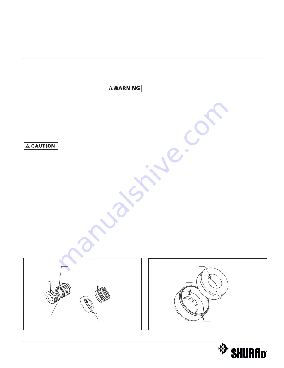
(Refer to Figure 13 for Reference
Numbers and Figures 3, 8, 9, 10, 11 & 12
for detailed seal and shaft assemblies.)
1. Remove pump from motor.
a. Remove the coupler half from the
pump (See Figure 3). The motor
coupler half does not need to be
removed unless motor is being
replaced.
2. Gear Removal
a. Remove cover plate (Ref. No. 2)
(held by eight screws) and gasket
(Ref. No. 3) if needed. Gently tap
cover plate with rubber mallet
to free it from dowel pins. Once
cover is removed, the idler shaft
and gear assembly can be pulled
out of pump body (Ref. No. 12).
b. Remove the idler gear (Ref. No.
6) from the shaft (Ref. No. 7) by
removing retaining rings (Ref.
No. 5), then slide gears off the
shaft end.
c. The drive gear (Ref. No. 6) can
be pulled out. Before drive shaft
(Ref. No. 9) can be removed
from body (Ref. No. 12), remove
Figure 10 - Seal Types and Parts Identification
Figure 11 - Seal Seat and Retainer Assembly
Mechanical Seal with
Seal, Spring & Retainer
(three loose pieces)
One-piece
Mechanical Seal
with Thru Boot
Ceramic Seat
with Rubber Cup
Seal Seat
(Ref. 14)
Notch in seat
aligned with pin
Anti-Rotation
Spring Pin
(Teflon Seals Only)
Seat Retainer
(Ref. 15)
Ceramic Seat
with O-ring
Polished Face
always goes against
Carbon Face of seal


