SHURflo 316 Stainless Steel Rotary
Close-Coupled External Gear Pumps
8
SHURflo Operating Instructions, Performance,
Specifications and Parts Manual
Viton Models GMSV2A, GMSV4A, GMSV6C, GMSV2A3T, GMSV2A33T,
GMSV4A5T, GMSV4A53T, GMSV6C7T and GMSV6C73T
Teflon
®
Models GMST2A, GMST4A, GMST6C, GMST2A3T, GMST2A33T,
GMST4A5T, GMST4A53T, GMST6C7T and GMST6C73T
Form L-4089 (2/17)
Installation
IMPORTANT: In any installations where
property damage and/or personal
injury can occur when the pump is
not operating due to power outages,
discharge line freezing, or any other
reason, a back-up system(s) and/or
warning system(s) should be used.
In order to safely use this product,
familiarize yourself with this pump and
also with the liquid (chemical, etc.)
that is going to be pumped through
the unit. This pump is not suitable for
many liquids.
1. Locate the pump as close to the
liquid source as possible, making
the suction line as short and direct
as possible.
PIPING
SUCTION
2. Avoid excessive lengths or number
of fittings and bends in the suction
line.
3. Attach suction line to suction inlet
(See Figure 1 for proper rotation).
4. It is recommended that same size
pipe as pump ports be used or, in
cases requiring lengthy piping, the
next larger size pipe be used.
5. If suction lift is greater than what is
indicated in the performance chart,
attach a foot valve below liquid
level at end of suction line to ensure
positive priming. Also note: If fluid
specific gravity is greater than 1.4 or
viscosity greater
than 500 SSU, a foot valve is also
recommended.
NOTE: If a foot valve (or check valve) is
not used in the suction line, it may be
necessary to refill the pump every time
the unit is stopped and you wish to restart
the pump. This depends on the length of
time between starts and whether or not
the gears are wet enough to close cavities
to affect a prime.
6. If solid contaminates are suspected
in a liquid, place a filter in the
suction line.
7. Be certain all suction piping connec-
tions are airtight.
NOTE: Assure airtight pipe connections
with the use of a pipe joint sealant.
DISCHARGE
8. Attach discharge piping to the
discharge outlet.
Support pump and
piping during assembly
and after installation.
Failure to do so may cause piping to break,
pump to fail, motor bearing failures, etc., all
of which can result in property damage and/
or personal injury.
NOTE: Should the pump need to be
self-draining, the pump head should be
mounted in the vertical position with
the suction port facing down. When
pumping high viscosity fluids, the
vertical position can be used with the
suction port facing up and the pump
mounted under the source. Increasing
the suction pipe size and eliminating
bends and elbows also assists in pump-
ing high viscosity fluids. Max. viscosity is
500 SSU at 1725 RPM.
9. If a shut-off valve or handgun is
required in discharge line, provide
a pressure relief valve for pump
protection.
Shutting off
discharge without
providing pressure
relief can cause extreme overpressure which
can result in pump and/or motor failure. Do
not exceed 125 PSI pump or system pres-
sure.
10. Operation under shut-off discharge
conditions will overheat and
damage pump.
NOTE: Globe valve or other restrictive
valves should not be used as shut-off
mechanism as they are restrictive in
nature and will seriously affect pump
performance.
11. After all piping and controls (not
supplied with unit) have been
installed, unit is ready for operation.
Operation
Do not run pump
dry, as permanent
damage to the pump
gears, seal, and
bearings will result. Suction pressure should
never be greater than the discharge pres-
sure.
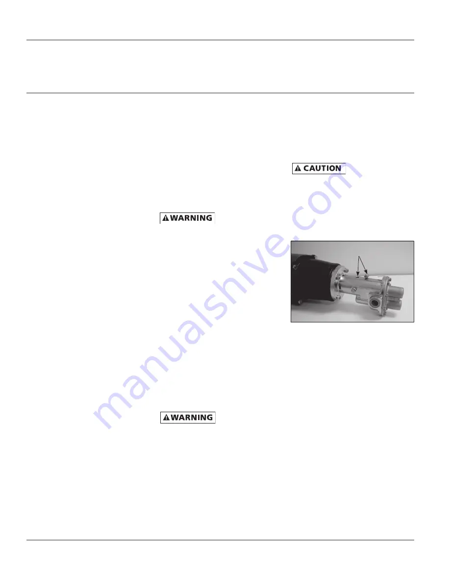
1. All pumps must be primed before
start-up and the seal chamber needs
to be filled (See Figure 5). Never
operate a pump unless it is secured
to a solid foundation and all safety
shields are installed.
Upon start-up, maintain a minimum
of 15 PSI (1 BAR) operating pressure
on the pump. This will allow any
remaining air to be driven from the
seal chamber and will ensure liquid
circulation to the mechanical seal.
2. Gear pumps are built to very close
tolerances and this tolerance must
not be altered. The liquids must,
therefore, be free of all abrasives.
Sand, silt, wettable powders, etc.
must be avoided.
3. When pumping a more viscous
(beyond 500 SSU) liquid; a slower
speed, a larger pipe size pump,
and possibly a larger motor should
be selected.
Figure 5 - Prime Plug
Remove plug and fill seal chamber
with fluid and reinstall plug


