


PT495 Series Detector
(Ultra1000)
Rev 5.11
18
Calibration
Refer to Table at the end of this section for the recommended calibration gas for
the target sensor. Also see section on Spare Parts for part numbers for other
calibration accessories.
Following items are needed for the sensor calibration:
•
Calibration adapter with tubing
•
Magnet tool to activate the switch on the transmitter board assembly.
•
Calibration gas bottle with flow regulator. The flow of the calibration gas
should be approximately 0.5 to 1 LPM (liters per minute)
See Figure 7 for setup
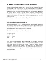
The sensor can be auto calibrated without removing the enclosure cover and
declassifying the zone. A magnet tool is used to activate the internal switch to
initiate the calibration. Once the calibration is initiated the alarm relays will be
inhibited and the 4-20mA analog signal will be held at approximately 2mA to
avoid any false alarm.
Calib
Mode
Magnet
ic W
an
d
Figure 6. Magnetic switch position to activate calibration Mode switch