Pelonis KCD25Y1 Instruction Manual Download Page 11

DRY( Dehumidifier) Operating Instructions
(cont'd)

plugged/capped

plug

drain

hose connector

Garden Hose

IMPORTANT:

fail-safe switch mechanism

reverse

re-cap/plug

internal

Failure to comply with these procedures will
result in flooding.

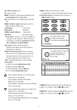
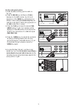
6) To connect the continuous drain option. Remove

the water tank from the cabinet. Inside the
cabinet (water tank area) you will find a section of
hose hanging beside the water tank, which is

at the end. Remove the

from the end of the hose and install the

(included with this unit) into the

end of this hose section. Route the end of the
hose (with drain connection) into the water tank,
then through the hole provided in the face of the
water tank. Attach a section of

(to

suit your continuous drain option requirements)
to the drain hose connector. Place the open end
of the hose directly over the drain area in your
basement floor. Fig.19.

Please make sure the drain hose

section routed through water tank does not interfere
with the correct positioning of the water tank inside
the cabinet, or the

will

be activated, not allowing the unit to operate.
7) You must remember to

the continuous

drain option procedure

the

(unplugged) inside the water tank,
when re-locating your unit to a location(room)
where continuous draining is not possible.

drain hose

the internal drain hose

and/or leave

Fig. 19

Garden Hose

(not included)

Drain Hose Connector

10

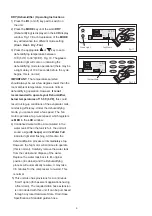
During air conditioning and dehumidifying modes, if the
compressor cycle is interupted (unplugged, power
failure, etc.) And reinstated immediately thereafter,(within
3-5 minutes.) A "compressor protection circuit"is
automatically self-affected. The mode indicator light will
flash "green" for approximately 10 seconds, confirming the
protection circuit is activated. The compressor cannot
operate during a "compressor protecton" condition.(this is
normal)It may take 3-5 minutes before the "protection
circuit" self-deactivates.

DO NOT ATTEMPT TO START THE UNIT
(COMPRESSOR)DURING THIS PERIOD.

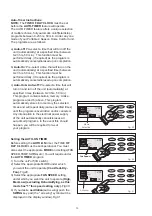
Removal and/or partial displacement of the water
tank will cause the compressor to stop operating
(this is a safety feature). This condition will cause
the unit to "beep 8"times"and the "water full"light
will flash

continuously until corrected.

Check the following;

1. Is the water tank full?

Empty and re-install water tank.

2. Has the water tank been accidently displaced?

Re-Position water tank.

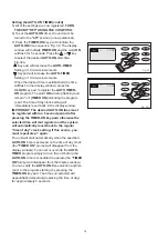
The "red" light will stop flashing automatically
When the water tank has been emptied and/or
correctly re-positioned.

(red)

The

compressor cannot operate during a flashing
"red" light condition.

CAUTION

ATTENTION

!

!

!

!

Summary of Contents for KCD25Y1

Page 1: ...PORTABLE AIR CONDITIONER INSTRUCTION MANUAL Read Rules for Safe Operation and Instructions Carefully...

Page 2: ......

Page 3: ...leave this unit unattended in a space where people or animals who cannot react to a failed unit are located A failed unit can cause extreme overheating or death in such an enclosed unattended space CA...

Page 4: ...d or servicing Electrical Specifications Unit Specifications Power Consumption Cooling Capacity Heating Capacity Dehumidifying Capacity Noise Level Power Source Refrigerant Water Tank Capacity Unit We...

Page 5: ...r the mode There should be at least 11 8 30 cm clearance between the unit and any other other objects or building structure The unit should be installed on a level surface The window kit does not have...

Page 6: ...the cabinet otherwise the unit will not operate Fig 4 5 To turn the unit on press the key On Off Switch Water Tank Safety Feature FULL 8 BEEPS WATER FULL This unit is equipped with a fail safe switch...

Page 7: ...adjust forward Time of Day Clock Used to adjust backward Time of Day Clock settings 1min increments settings 1min increments Used to adjust forward Temperature Used to adjust backward Temperature set...

Page 8: ...clock program In the event this should happen you will be required to re set the clock program 1 Install the Fig 10 and the as depicted in Fig 2 2a 2b pg 5 2 Press the I O on off key pad to switch on...

Page 9: ...perature level The temperature has no effect on the fan operation Therefore the fan will operate continuously after the compressor has cycled off to maintain optimal temperature control 12 00 00 TIMER...

Page 10: ...cannot select a fan speed The fan motor operates at a pre set speed which registers as in the window 4 Condensed water will be accumulated in the water tank When the tank is full the unit will sound...

Page 11: ...nk when re locating your unit to a location room where continuous draining is not possible drain hose the internal drain hose and or leave Fig 19 Garden Hose not included Drain Hose Connector 10 Durin...

Page 12: ...the key to activate the automatic air swing oscillating feature the air swing symbol will appear in the window Fig 23 To deactivate the air swing feature press the key again 5 To adjust air flow direc...

Page 13: ...ection will be displayed in the window Each depression of the fan key will advance to a different speed 4 Press the key to activate the automatic air swing oscillating feature the air swing symbol wil...

Page 14: ...ridden and or canceled Any interruption to the electrical power supply of the unit automatically cancels erases all auto timed programs In the event this should happen you will be required to re set y...

Page 15: ...ime Fig 32a Key pad will decrease the Setting in 10 minute increments Keypad will increase the Setting in 10 minute increments When the desired time is established the time will flash in the display w...

Page 16: ...he or key pad to select the desired start Fig 33a Key pad will decrease the Setting in 10 minute increments Keypad will increase the Setting in 10 minute increments When the desired time is establishe...

Page 17: ...d to select the desired time Fig 32a Key pad will decrease the setting in 10 minute increments Key pad will decrease the setting in 10 minute increments When the desired time is established the time w...

Page 18: ......

Page 19: ......

Page 20: ......

Page 21: ......

Page 22: ......

Page 23: ......

Page 24: ......

Page 25: ...ull the filter out then up Fig 34 3 Dust Dirt clogged in the filter can be removed by vacuum cleaning the soiled areas 4 The filter can also be washed in lukewarm soapy water while rubbing it lightly...

Reviews: