background image

6“ from end 

Lip 

#6 x 5/8” corrosion 
resistant screws 

2B

ALL

 DOORS •

 ALL

 DOORS •

 ALL

 DOORS •

 ALL

 DOORS

3

SETTING AND FASTENING THE DOOR

B. 

Cut and remove the strap that runs

 from the 

door lock to the sill of the door.

C. 

Insert the door from the exterior of the building 
DO NOT

 slide the bottom of the door into the 

opening. Sliding will damage the sealant lines. Place 
the bottom of the door at the bottom of the opening 
with the door centered between the sides of the 
opening to allow for shimming, then tilt the top into 
position. Insert one 16d galvanized fi nishing nail at 
each upper corner of the brickmould. These are used 
to hold the door in place while shimming it plumb 
and square. 

TWO OR MORE PEOPLE WILL BE REQUIRED FOR THE FOLLOWING STEPS.

&YUFSJPS

Ó

3C

EXTERIOR SILL P

AN LIP 

INTERIOR SILL P

AN LIP 

2nd Bead 

Leave a 2" break  
in center of pan 

1st Bead 

3rd Bead 

3A 

6”

A.  

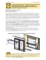
Place three 3/8" beads of sealant.

 Place 

the fi rst bead of sealant 1/2" from the base 
of the interior sill pan lip. This bead should 
also continue up the corner of the sill pan 
at each end, sealing the vertical joints of 
the sill pan legs. Continue the fi rst bead  
up 6" onto each jamb side of the rough 
opening. The second bead should be 
approximately 1/2" from the exterior edge 
of the rough opening, running from jamb 
to jamb with a 2" break in the middle of the 
opening. Place a third sealant bead in the 
groove of the sill support from end to end 
or 1/4" from the exterior edge of the wood 
blocking. 

B. 

Doors using Installation Clips:


Install installation clips. Place  each 
clip so the lip is facing up and against 
the brickmould at the locations 
shown in the placement diagram. 
Secure each clip by driving a #6 
x 5/8" corrosion resistant screw 
through each of the outer two holes 
of the three holes shown. 

Note: If clips are to be bent; pre-
bend before attaching to frame.

3B

6”

1

2

3

3A

Applications without sill pan

PERFORMANCE UPGRADE


Note: Sill sealant detail is the same for 
applications with and without optional sill pan.

Summary of Contents for 818K0100

Page 1: ...her construction methods multiple units or bow and bay windows may be obtained from Pella Corporation or a local Pella retailer or by visiting http www pella com Building designs construction methods...

Page 2: ...ers 2 Phillips with 8 shaft and small at blade T20 Torx Wrench Drill Drill bits 13 64 and 1 8 and masonry bit for concrete applications INSTALLATION CLIP OPTION 6 or 8 installation clips 6 x 5 8 corro...

Page 3: ...Apply sill ashing tape 1 Cut a piece of ashing tape 12 longer than the opening width Apply at the bottom of the opening as shown 1E so it overhangs 1 to the exterior Note The tape is cut 12 longer tha...

Page 4: ...g tape to the width of the opening Install to the anges of the sill pan and overlap the tape from step 1N by 1 If needed add a second or third piece of ashing tape until the sill pan is covered to the...

Page 5: ...ons for Performance Upgrade and HurricaneShield product requires additional clip installation or screw installation Clip installation prep is included in Step 2B Screw installation steps are included...

Page 6: ...of sealant Place the rst bead of sealant 1 2 from the base of the interior sill pan lip This bead should also continue up the corner of the sill pan at each end sealing the vertical joints of the sil...

Page 7: ...ly open the door s and remove all shipping spacers Note Be sure to remove the spacers from the bottom edge of the door panel Use the construction handle to operate both the active and passive door pan...

Page 8: ...the open screw hole Make sure the screw passes through the shims and into the structural framing M Check door operation Open and close the door to check for proper operation Make sure the door will l...

Page 9: ...oximately 8 from the top of the door frame head Insert a 8 x 3 screw provided into the pilot hole making sure it passes through the shim and into the rough opening framing Note This step does not appl...

Page 10: ...rough opening in the locations shown On hinge jambs clearance hole locations are centered between hinges Hinge Jambs See 5A In Swing diagram upper right Fixed and Lock jambs diagram for placement of t...

Page 11: ...nufacturers s recommendations NOTE Not required on In swing Fixed doors Out Swing SILL HEAD Drill 1 8 diameter pilot holes through the clearance hole in the frame 5C 10 x 3 1 2 corrosion resistant woo...

Page 12: ...into the space between the door and the rough opening and apply a 1 deep bead of foam This will allow room for expansion of the foam and will minimize squeeze out Apply sealant across the interior sur...

Page 13: ...s with window and door materials and voids Limited Warranty For additional information on nishing see the Pella Owner s Manual or go to www pella com EXTERIOR FINISHING Wood doors require painting imm...

Page 14: ...management of moisture within the wall systems The determination of the suitability of all building components including the use of Pella products as well as the design and installation of ashing and...

Page 15: ...This page left blank intentionally...

Page 16: ...This page left blank intentionally...

Reviews: