Chapter. 1
– Introduction
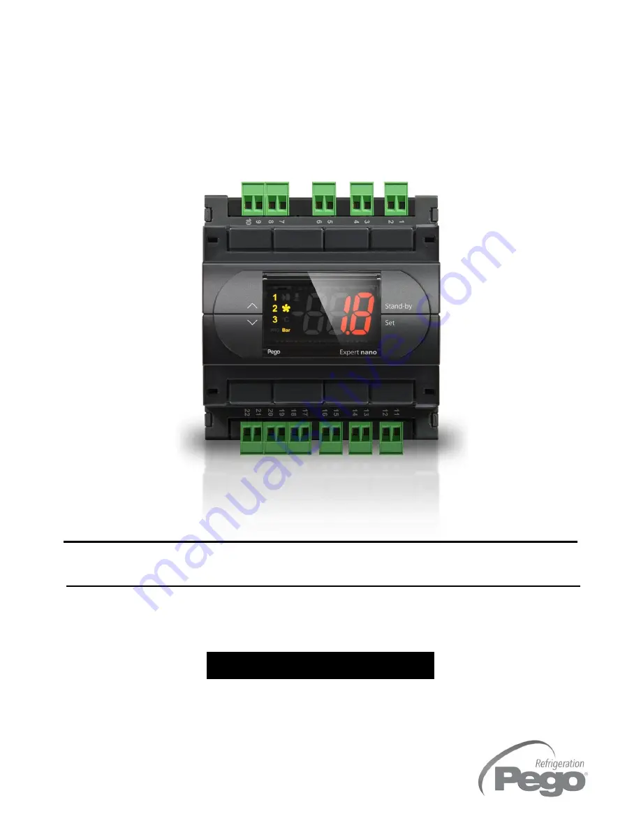
DIN NANO FSC
USER AND MAINTENANCE MANUAL
Page 1
REV. 01/04
User and maintenance manual
ENGLISH
ELECTRICAL BOARDS FOR REFRIGERATING INSTALLATIONS
READ AND KEEP
REV. 03-18
ENG
200
NDINFSC
Electronic regulator on DIN bar
to manage condenser fans


