background image

E

LECTRICAL

 I

NFORMATION

Combination Warmer   

   Operator’s Manual   

   M N-47424   

   Rev 1   

   4/21

58

Continued from previous page

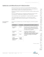
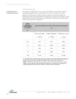
Electromagnetic 

immunity distance

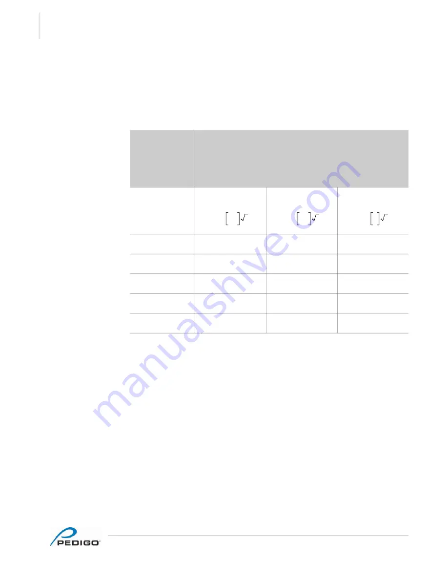
The warmer is intended for use in an electromagnetic environment in which 

radiated RF disturbances are controlled. The user of the warmer can help 

prevent electromagnetic interference by maintaining a minimum distance 

between portable and mobile RF communications equipment (transmitters) and 

the warmer as recommended below, according to the maximum output power 

of the communications equipment.


Rated 

maximum 

output power of 

transmitter

W

Separation distance according to frequency of transmitter

m

150 kHz to 80 MHz

80 MHz to 800 MHz

800 MHz to 2.5 GHz

0.01

0.117

0.117

0.233

0.1

0.369

0.369

0.738

1

1.167

1.167

2.333

10

3.689

3.389

7.379

100

11.667

11.667

23.333

For transmitters rated at a maximum output power not listed above, the recommended separation distance d in 

meters (m) can be estimated using the equation applicable to the frequency of the transmitter, where P is the 

maximum output rating of the transmitter in watts (W) according to the transmitter manufacturer.

NOTE: 

At 80 MHz and 800 MHz, the separation distance for the higher frequency range 

applies. These guidelines may not apply in all situations. Electromagnetic propagation is 

affected by absorption and reflection from structures, objects and people.

d

3.5

3

-------

P

=

d

3.5

3

-------

P

=

d

7
3

---

P

=

Summary of Contents for P-2420

Page 1: ...Operator s Manual Combination Blanket Fluid Warmer P 2420 P 2430 18 Depth and 24 Depth MN 47424 REV 01 4 21 EN...

Page 2: ...reproduced or used in any manner whatsoever without the express written permission of Pedigo Products Inc Trademarks All trademarks referenced in this documentation are the property of their respectiv...

Page 3: ...e most durable convenient efficient and safe warming equipment on the market All warmers are manufactured and fully inspected in the USA with a commitment to quality Pedigo Repair Service Call Call 26...

Page 4: ...FOREWORD Combination Warmer Operator s Manual MN 47424 Rev 1 4 21 4 This page intentionally left blank...

Page 5: ...ilt In Warmer into the Wall 28 Operation 31 Preparing the Warmer for First Use 31 How to Turn On and Turn Off the Warmer 32 How to Operate the TriMode Warmer 33 How to Change the Temperature Scale 35...

Page 6: ...FOREWORD Combination Warmer Operator s Manual MN 47424 Rev 1 4 21 6 This page intentionally left blank...

Page 7: ...DANGER Danger indicates a hazardous situation which if not avoided will result in serious injury or death WARNING Warning indicates a hazardous situation which if not avoided could result in serious i...

Page 8: ...r Do not use this warmer for warming blood or blood products Do not cover or block any of the openings of this warmer Do not use this warmer in a wet location Only clean the warmer when the power cord...

Page 9: ...hed to or shipped with the warmer Only trained personnel are permitted to service or repair the warmer Repairs that are not performed by a trained technician or the use of non factory parts will void...

Page 10: ...SAFETY Combination Warmer Operator s Manual MN 47424 Rev 1 4 21 10 This page intentionally left blank...

Page 11: ...LABELS Combination Warmer Operator s Manual MN 47424 Rev 1 4 21 11 L ABELS Label Locations EC PHD 011147 a c d b...

Page 12: ...ical warning label 3 Pedigo contact information 4 Quality inspected S e c u r i t y S e a l S e c u r i t y S e a l S e c u r i t y S e a l S e c u r i t y S e a l S e c u r i t y S e a l S e c u r i...

Page 13: ...al shock fire and mechanical hazards only in accordance with UL 61010 1 and CAN CSA C22 2 No 61010 1 Grounding reliability can only be achieved when the appliance is connected to an equivalent recepta...

Page 14: ...ith Standard Feet EC DIM 011150 IEC Cord Inlet Cord length 6 ft 1 83m est 30 0 762mm 30 0 762mm 26 6 674 5mm 24 44 620 7mm 60 0 1524mm 51 12 1298 6mm 24 41 620mm CAVITY INSERT 16 43 417 4mm INSERT 25...

Page 15: ...4 21 15 18 Depth P 2420 shown with Optional Caster Plate 18 Depth P 2420 shown with Optional Caster Plate with Bumpers EC DIM 011162 29 6 752mm 5 0 128mm 26 9 683mm IEC Cord Inlet EC DIM 011165 29 6...

Page 16: ...In EC DIM 011156 30 0 762mm 30 0 762mm 26 6 674 5mm 24 44 620 7mm 60 0 1524mm 47 55 1207 8mm 24 34 618 24mm CAVITY INSERT 16 43 417 4mm INSERT 18 27 464mm CAVITY 16 9 429 34mm CAVITY 18 8 479 2mm 20...

Page 17: ...ire temperature of 80 C NOTICE Built in units must be hardwired to the facility mains with a 15A breaker switch Breaker Wire Size Wire Temperature 15A 12 AWG 1mm2 80 C minimum Electrical connections m...

Page 18: ...SPECIFICATIONS Combination Warmer Operator s Manual MN 47424 Rev 1 4 21 18 Continued from previous page EC DIM 011159 24 0 609 6mm 29 25 743mm 18 0 457 2mm 3 0 76 2mm 3 0 76 2mm 6 0 152 4mm 1 2 3...

Page 19: ...t and 1 shelf optional for 24 depth P 2430 EC DIM 011168 IEC Cord Inlet Cord length 6 ft 1 83m est 30 0 762mm 30 0 762mm 26 6 675mm 24 47 621 5mm 60 0 1524mm 57 12 1298 6mm 24 41 620mm CAVITY INSERT 1...

Page 20: ...th Bumpers NOTE 1 shelf standard for 24 depth P 2430 1 basket and 1 shelf optional for 24 depth P 2430 EC DIM 011171 29 6 752mm 5 0 128mm 26 9 683mm IEC Cord Inlet 17 0 432mm USABLE HEIGHT 8 25 210mm...

Page 21: ...ilt In EC DIM 011177 30 0 762mm 30 0 762mm 26 6 674 5mm 24 47 621 5mm 60 0 1524mm 53 5 1360 2mm 24 34 618 24mm CAVITY INSERT 17 52 445mm INSERT 18 27 464mm CAVITY 16 9 429 34mm CAVITY 24 85 631mm 26 2...

Page 22: ...wire temperature of 80 C NOTICE Built in units must be hardwired to the facility mains with a 15A breaker switch Breaker Wire Size Wire Temperature 15A 12 AWG 1mm2 80 C minimum Electrical connections...

Page 23: ...SPECIFICATIONS Combination Warmer Operator s Manual MN 47424 Rev 1 4 21 23 Continued from previous page EC DIM 011180 24 0 609 6mm 29 25 743mm 24 0 609 6mm 3 0 76 2mm 3 0 76 2mm 8 0 203 2mm 1 2 3...

Page 24: ...SPECIFICATIONS Combination Warmer Operator s Manual MN 47424 Rev 1 4 21 24 This page intentionally left blank...

Page 25: ...he box or crate Save all packing materials for inspection by the carrier 2 Cut and remove the retaining straps and plastic wrap 3 Remove the warmer from the pallet using an appropriate lifting device...

Page 26: ...r do the following Step Action 1 Make sure that The location where the warmer is being installed is rated to support the weight of the warmer The warmer is within five feet of the appropriate electric...

Page 27: ...previous page Connect power To connect electric power to the warmer do the following 4 Connect the plug to the electrical outlet Result The warmer is now installed and ready to be used NOTE For built...

Page 28: ...d position the weight of the warmer 3 Phillips screwdriver Supplied 2 SC 47298 wall screws Procedure To install the built in warmer into the wall do the following Step Action 1 After wiring the warmer...

Page 29: ...o release the interface bends that are locked by the tabs 4 Secure the warmer to the wall using the two 2 self tapping wall screws SC 47298 b and a 3 Phillips screwdriver 5 Re install the interface as...

Page 30: ...Combination Warmer Operator s Manual MN 47424 Rev 1 4 21 30 Continued from previous page 6 Re install the screws c to the interface panel Result The built in warmer is now installed into the wall EC...

Page 31: ...f stainless steel panels with an approved cleaning agent if painted panels 3 Clean the interior of the warmer with a damp cloth or approved cleaning agent 4 Dry the interior and exterior of the warmer...

Page 32: ...he power switch a to the ON l position 2 Press the standby button The screen turns on The warmer is now on Turning off the warmer To turn off the warmer do the following 3 Press and hold the standby b...

Page 33: ...icon will not illuminate Continued on next page WARNING Personal injury hazard Do not operate the warmer in the presence of a flammable anesthetic mixture with air oxygen or nitrous oxide in oxygen en...

Page 34: ...process 4 Press the temperature recall button to view the measured cavity temperature The measured cavity temperature will display for five seconds Then the set point temperature will display Result...

Page 35: ...release the button 3 Press the up and down arrow buttons to toggle between the temperature scales 4 Press the standby button to turn the screen on Result The temperature scale has now been changed How...

Page 36: ...following Step Action 1 Press and while holding the standby button press the up arrow button The lock indicator will illuminate Unlocking the controller To unlock the controller do the following 2 Pr...

Page 37: ...iple years of data The download time for one week of data should be under five seconds The warmer records various performance parameters during the following conditions automatically every five minute...

Page 38: ...rom the port 4 Close the warmer door Result The data has now been downloaded Viewing the temperature data To view the temperature data do the following 5 Plug the USB drive into a computer 6 Double cl...

Page 39: ...70 9 104 Diagnostics SensorSho rtErrors 0x0c 5 1 2019 9 01 bottom INJ on closed on 69 9 104 Diagnostics SensorSho rtErrors 0x0c 5 1 2019 9 02 bottom INJ on closed on 69 3 104 Diagnostics SensorSho rtE...

Page 40: ...OPERATION Combination Warmer Operator s Manual MN 47424 Rev 1 4 21 40 This page intentionally left blank...

Page 41: ...nance do the following Check the door gasket for tears and holes Make sure that it is firmly attached to the door Check the seal when the door is closed the guards around the air temperature sensor ar...

Page 42: ...re with a thermocouple placed 1 25mm from the cavity sensor Do not allow the thermocouple to touch any surface Monitor the temperature for approximately one hour in an empty cavity the condition of th...

Page 43: ...rmer with a damp cloth or approved cleaning agent 5 Dry the interior and exterior of the warmer with a clean lint free cloth Leave the door open until the interior of the warmer completely dries 6 Cle...

Page 44: ...mer cavity 4 Clean the shelves and interior with a damp cloth or approved cleaning agent 5 Dry the interior of the warmer with a clean lint free cloth Leave the door open until the interior of the war...

Page 45: ...er Operator s Manual MN 47424 Rev 1 4 21 45 Warmer Disposal Decommissioning This product and its accessories must be disposed of according to local laws and regulations Do not dispose of this product...

Page 46: ...MAINTENANCE Combination Warmer Operator s Manual MN 47424 Rev 1 4 21 46 This page intentionally left blank...

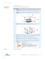
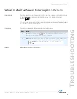
Page 47: ...s The controller stores all settings and continues operation using these settings in the event of a power interruption Procedure To continue operation of the warmer do the following Step Action 1 Pres...

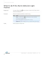
Page 48: ...sounds an alarm when the warmer malfunctions Procedure If the alarm indicator light flashes do the following Step Action 1 Press the standby button to acknowledge and mute the alarm The alarm indicat...

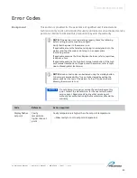
Page 49: ...o topic How to Replace a Fuse If applicable examine the high limit manual reset button If the high limit manual reset button is tripped reset the warmer refer to topic How to Manually Reset the Warmer...

Page 50: ...connect the sensor from the warmer control PCB and use an Ohm meter to measure the resistance of the sensor Sensor PR 37140 should measure 10 KOhm 1 5 KOhm at 25 C 77 F Sensor SN 33541 should measure...

Page 51: ...lanket warmers only Real time clock rechargeable battery backup has discharged Plug the warmer into the outlet for 30 minutes E 61 Real Time Clock Blanket warmers only Real time clock not responding C...

Page 52: ...clean and operating correctly Set the power switch to the OFF position to clear the error code If error persists the cavity sensor should be replaced by a qualified service technician Contact service...

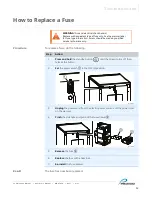
Page 53: ...n 3 Unplug the power cord from the electric power source and the power inlet on the warmer 4 Pinch the side tabs and pull out the fuse drawer b 5 Remove the fuse c 6 Replace the fuse with a new fuse 7...

Page 54: ...TROUBLESHOOTING Combination Warmer Operator s Manual MN 47424 Rev 1 4 21 54 This page intentionally left blank...

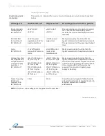
Page 55: ...of the warmer is to not exceed an internal temperature of 180 F 82 C for blanket warmers or 150 F 66 C for fluid warmers Electromagnetic emissions The warmer is intended for use in the electromagneti...

Page 56: ...fferential mode 2 kV common mode 1 kV differential mode 2 kV common mode Mains power quality should be that of a typical commercial or hospital environment Voltage dips short interruptions and voltage...

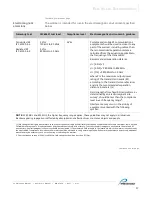
Page 57: ...transmitters as determined by an electromagnetic site survey1 should be less than the compliance level in each frequency range2 Interference may occur in the vicinity of equipment marked with the fol...

Page 58: ...distance according to frequency of transmitter m 150 kHz to 80 MHz 80 MHz to 800 MHz 800 MHz to 2 5 GHz 0 01 0 117 0 117 0 233 0 1 0 369 0 369 0 738 1 1 167 1 167 2 333 10 3 689 3 389 7 379 100 11 667...

Page 59: ...containing chloride or quaternary salts poor water quality or equipment with missing or altered serial numbers Any losses or damage resulting from malfunction including loss of contents or consequenti...

Page 60: ......

Page 61: ......

Page 62: ......

Page 63: ......

Page 64: ...igo Products Inc 4000 S E Columbia Way Vancouver WA 98661 Phone 800 822 3501 Fax 360 696 1700 www pedigo usa com Made in the U S A Printed in the U S A Specifications are subject to change without not...

Reviews: