


8
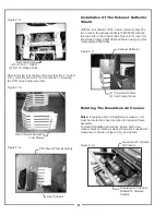
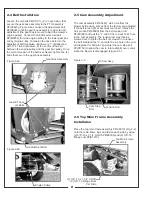
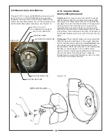
2-4 Belt Installation
Loosen the (4) bolts P#(K1191), (2) on each side, that
secure the gear box assembly to the PTO assembly
P#(A0623) (Figure 2-4a). Loosen the adjustment bolt
P#(K0348) until the gear box assembly is at its far left
adjustment (the gear box is moved toward the mower’s
engine pulley). Connect the A63K kevlar cord belt
P#(M0252) from the engine pulley to the lower gear box
pulley (Figure 2-4b). To tension the drive belt, turn the
adjustment bolt clockwise until there is 1” of deflection,
with 10-11 lbs. of pressure, at the center of the belt
between the engine pulley and the gear box pulley. Once
the correct tension of the belt is achieved, tighten the (4)
bolts that secure the gear box assembly.
Gear Box Assembly
Adjustment Bolt
Loosen These
(4) Bolts
Engine Pulley
Figure 2-4a.
Figure 2-4b.
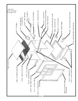
Top Main Frame
Assembly
(2) 3/8” -16 x 1-1/4” HHCS
(2) 3/8”-16 Flange Nuts
Per Side
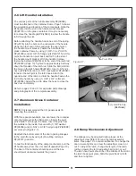
2-5 Cam Assembly Adjustment
The cam assembly P#(A0422), which controls the
blower belt tension, comes from the factory pre-adjusted.
If the belt is too tight or becomes too loose, remove the
hair pin clip P#(K0099) from the belt tension rod
P#(K0326) and pull the “L” end of the rod out of it’s hole
in the cam assembly. The tension rod may then be
screwed out to tighten the belt or screwed in to loosen
the belt. Replace the “L” end into the top hole in the cam
and replace the hair pin clip. Adjust the cam stop bolt
P#(K1159) to allow the cam to rotate slightly over center
when the blower is disengaged (Figure 2-5).
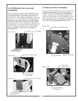
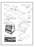
2-6 Top Main Frame Assembly
Installaton
Place the top main frame assembly P#(A0618) (Fig. 2-2)
onto the main frame legs and fasten each side by using
(2) 3/8”-16 x 1-1/4” HHCS P#(K0309) and (2) 3/8”-16
flange nuts P#(K1215).
Cam Assy.
Tension Rod
Figure 2-5.
Cam Stop
Bolt
Summary of Contents for 50721201
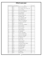
Page 14: ...PTO Parts List 14...
Page 21: ...21...


