Peco 50721201 Operator'S Manual Download Page 3

3

SAFETY

WARNING! 

NEVER 

operate the mower unless the discharge guard and either the deflector assembly or the 

vacuum collector adapter are fastened securely in place.

WARNING!


Do not work around the mower deck boot or the blower area until you are certain that the mower 

blades and the blower impeller have stopped rotating.

WARNING!


To avoid serious injury, perform maintenance on the vacuum collector; 

ONLY AFTER 

STOPPING THE MOWER’S ENGINE AND WAITING FOR ALL MOVING PARTS TO COME TO A 

COMPLETE STOP. 

Set the parking brake. Always remove the ignition key before beginning maintenance.

WARNING!


For your own personal safety,

 ALWAYS 

mow

 ACROSS 

the face of slopes and 

NEVER UP 

AND DOWN

 the face.

 NEVER 

attempt to mow excessively steep slopes, and use caution when turning on any slope.

Safety Alert Symbol


This Safety Alert Symbol means:

 “ATTENTION! BECOME


ALERT! YOUR SAFETY IS INVOLVED!”


This symbol is used to call attention to safety precautions that


Should be followed by the operator to avoid accidents. When


you see this symbol, carefully read the message that follows


and heed its advice. Failure to comply with safety precautions


could result in death or serious bodily injury.

Safety Signs

The signal words

 DANGER, WARNING, 

and

 CAUTION 

are used on the equipment safety signs. These words are 

intended to alert the viewer to the existence and the degree of hazard seriousness. 

!

DANGER

!

WARNING

!

CAUTION

!

This signal word indicates a potentially hazardous situation which, if not 
avoided, will result in death or serious injury.

This signal word indicates a potentially hazardous situation which, if not 
avoided, could result in death or serious injury.

It may also be used to alert against unsafe practices.

This signal word indicates a potentially hazardous situation exist which, if 
not avoided, will result in minor or moderate injury.

It may also be used to alert against unsafe practices.

White letters on

 RED

Black letters on

 ORANGE

Black letters on

 YELLOW

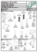
Summary of Contents for 50721201

Page 1: ...OPERATOR S MANUAL PTO GRASS COLLECTION SYSTEM DESIGNED FOR ASSEMBLY OPERATION MAINTENANCE MODEL 50721201 EVERRIDE WARRIOR SERIES MOWER MANUAL PART Q0351 4 00 REV 0 P PECO PECO P P P P PECO PECO PECO...

Page 2: ...when the container is empty 11 Inspect your lawn and remove any foreign objects before mowing Never deliberately run the mower across any foreign object 12 Wear ear protection if the noise level is of...

Page 3: ...LVED This symbol is used to call attention to safety precautions that Should be followed by the operator to avoid accidents When you see this symbol carefully read the message that follows and heed it...

Page 4: ...ttached to PECO products are covered under a separate warranty by the respective manufacturer D UNAPPROVED ALTERATION OR MODIFICATION All obligations of PECO Inc under this warranty shall be terminate...

Page 5: ...Once the container is full of clippings the operator can easily push and raise the lift handle releasing the container s rear door and the container will pivot towards the ground Section II INSTALLAT...

Page 6: ...nlet clamp plates P B1668 Figure 2 1f Rotating The Donaldson Air Cleaner Note If equipped with a Donaldson air cleaner unit must be rotated to make clearance for top main frame assembly To rotate Dona...

Page 7: ...ame leg P B0343 See Figure 2 2c 9 7 4 3 8 16 x 1 1 4 HHCS 2 3 Universal PTO Installation To mount the PTO assembly insert the mount rod on the PTO assembly P A0623 into the mounting slots located on t...

Page 8: ...ley Figure 2 4a Figure 2 4b Top Main Frame Assembly 2 3 8 16 x 1 1 4 HHCS 2 3 8 16 Flange Nuts Per Side 2 5 Cam Assembly Adjustment The cam assembly P A0422 which controls the blower belt tension come...

Page 9: ...lot of the handle mount bracket With the handle in place fasten the ball joint P K1442 to the end of the latch rod P A0260 Page 10 Tighten to approximately half way down the threads of the latch rod S...

Page 10: ...10 INLET RING Figure 9 Lift Handle Assembly Figure 10 Aluminum Grass Container With Handle Attached Figure 11 Latch Hook Mechanism Assembly Figure 12 Aluminum Grass Container Assembly...

Page 11: ...193 LINKAGE ROD J0176 LATCH SPRING J0522 HANDLE GRIP A0574 BOX HANDLE V1152 INLET RING W LOCKING PIN B8113 SCREEN B0205 BASE FRAME B1529 LATCH HOOK B0192 BASE FRAME PIVOT MOUNT K1442 ADJUSTING BALL JO...

Page 12: ...ARDWARE BAG 1 HB0266 HARDWARE BAG A0693 WEIGHT KIT A0694 BOOT KIT 1 HB0265 ENGINE PULLEY HARDWARE BAG 1 HB0267 HARDWARE BAG 2 B0318 WEIGHT BRACKET MOUNT 1 LT 1 RT B0317 WEIGHT BRACKET 1 B0331 BOOT PLA...

Page 13: ...xploded Parts View 28 31 30 27 29 34 35 33 8 23 24 6 32 12 2 2 2 2 2 7 7 11 21 10 1 3 3 3 3 3 3 3 3 9 4 5 15 25 25 25 25 25 25 16 16 16 16 26 22 17 17 17 17 17 17 17 17 17 17 17 17 20 20 14 13 19 18 1...

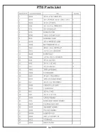
Page 14: ...PTO Parts List 14...
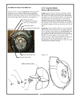
Page 15: ...venly into the taper lock bushing forcing the blade to break away from the taper lock bushing If the impeller will not move hit the base of the impeller between each vein with a hammer then try again...

Page 16: ...ad of the bolt is placed from the inside of the boot This will prevent grass from collecting on the bolts Remove the bolts that hold the deflector shield in place so that the boot rod can fasten the b...

Page 17: ...elf approximately 1 to add in retaining boot to mower deck 2 16 Front Weight Installation Secure the weight brackets P B0317 to the mower by using 1 weight bracket mount P B0318 2 3 8 16 x 1 1 4 HHCS...

Page 18: ...4 and 2 5 of the manual 3 4 Unloading The Collection System NOTE Press the tab located behind the operator s left side downward to feel if the collection system is full If the container is full there...

Page 19: ...placement parts accessories and do any service or repairs to your collection system If for any reason your Service Center is unable to service your collection system or supply replacement parts contac...

Page 20: ...n occur to safety decals either through shipment use or reconditioning Contact your local Service Center for replacement decals Part R1054 Part R1052 Part R1049 Part R1057 Part R1053 Part R1055 Part R...

Page 21: ...21...

Page 22: ...100 AIRPORT ROAD ARDEN NORTH CAROLINA 28704 800 438 5823 OR 828 684 1234 FAX 828 684 0858 EMAIL peco lawnvac com WEBSITE www lawnvac com P PECO PECO P P P P PECO PECO PECO...

Reviews: