
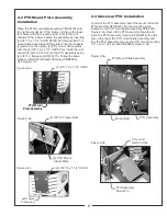

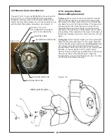
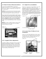


2-13 Upper Hose Installation
Slide (1) 5”-6” upper hose clamp P#(J6011) onto both
ends of the 6” upper hose. Place (1) hose ring
P#(E0007) into one end of the 6” hose making sure the
hose is on at least 2”, then tighten the hose clamp.
Proceed to slide the opposite end of the 6” hose onto the
blower assembly and tighten hose clamp. Place the
hose ring onto the inlet ring and tighten the locking pin.
See Figure 2-13 for details. Make sure both ends of the
hose are securely fastened to the inlet and the blower
assembly outlet.
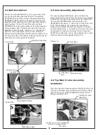
2-14 Lower Hose To Blower Cone
Installation
Slide a 7”-8” hose clamp P#(J6006) over both ends of
the lower hose. Then proceed to slide the lower hose
onto the blower cone. Tighten the hose clamp. The
assembly should look like (Figure 2-14).
16
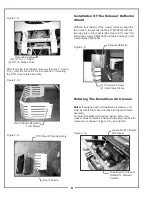
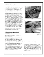
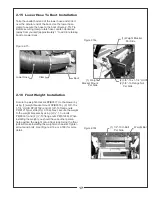
2-11 Boot To Mower Deck Installation
To mount the boot plate P#(B0331) to the boot
P#(E1113) use (3) 3/8”-16 x 1” carriage bolts P#(K1182)
and (3) 3/8”-16 flange nuts P#(K1215). See Figure 2-11
for bolt placement.
NOTE:
When bolting the boot and boot plate together,
the head of the bolt is placed from the inside of the boot.
This will prevent grass from collecting on the bolts.
Remove the bolts that hold the deflector shield in place
so that the boot rod can fasten the boot and boot plate to
the mower deck. Align the holes in the boot plate to the
holes in the deflector shield mount and slide the Warrior
boot rod P#(B2540) or the Hornet boot rod P#(B0333)
through the deflector shield and boot plate. Fasten by
using (1) hair pin clip P#(K0099) as shown in the figures
below.
NOTE:
The mower’s deflector shield is removed in the
following photo for clarity. Always have the deflector
shield mounted when mowing.
2-12 Length Of Hose Adjustment
The hoses in steps 2-13 and 2-14 must be cut to fit your
machine. Follow steps 2-13 and 2-14. do not cut the
hoses until you have tried to fit them on your machine.
Remember that the hoses have to be long enough to
adjust for the blower assembly’s movement as well as
allow for enough clamping surface between the inlet,
blower assembly, and the deck boot.
Boot
Boot Plate
Hair Pin Clip
Boot Rod
Figure 2-11.
Figure 2-14.
Figure 2-13.
Inlet Ring W/Locking Pin
6” Hose Ring
5”-6” Hose Clamp
6” Upper Hose
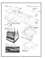
INLET
UPPER
HOSE
BLOWER
CONE
LOWER
HOSE
BOOT
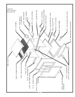
Summary of Contents for 50721201
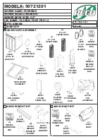
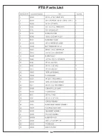
Page 14: ...PTO Parts List 14...
Page 21: ...21...


