


9
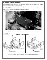
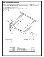
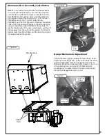
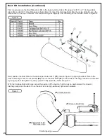
Note: Leave all hardware relatively loose until the end of the next step. Some parts and features have been hidden
from view for visual clarity.
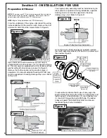
Position the Bottom Bracket / Mount Arm (Item #1) under the Top Bracket / Mount Arm and align the bolt holes of the
Bottom Bracket / Mount Arm to the bolt holes located on the bottom right rear of the mower. Refer to Figure A. Secure
the Bottom Bracket / Mount Arm by using (3) 3/8”-16 x 1-1/4” Carriage Bolts (Item #2) and (3) 3/8”-16 Ny-Flange Lock
Nuts (Item #3).
Bottom Bracket / Mount Arm Installation
Figure A
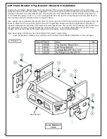
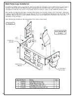
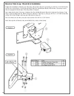
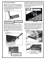
Rear Frame Bracket Installation
Position the Rear Frame Bracket (Item #1) between the Left Frame Bracket & Top Bracket / Mount Arm and align the
bolt holes. Loosely secure the Rear Frame Bracket by using (6) 3/8”-16 x 1” Carriage Bolts (Item #2) and (6) 3/8”-16
Ny-Flange Lock Nuts (Item #3). Once the Rear Frame Bracket has been loosely secured, tighten all hardware at this
time.
Figure A
Top Bracket /
Mount Arm
Bottom Bracket /
Mount Arm
Bottom Bracket / Mount Arm Positioning
Tighten All
Hardware at
This Time
Leave Hardware
Loose
Summary of Contents for 23651201
Page 24: ...24 Wire Harness Installation Continued Figure D...
Page 27: ...27 A2207 Mount Arm Tube Assembly...
Page 32: ...32 A2060_01 Mounted Drive Assembly...
Page 34: ...34 A2061_02 Drive Assembly 4 Blade Impeller...
Page 37: ...37...
Page 41: ...41...
Page 43: ...43 Notes...