Peco 23651201 Operator'S Manual Download Page 4

4

A.  WHAT IS UNDER WARRANTY?

2.  PARTS REPLACED DURING WARRANTY:

 Any new PECO part which is furnished in performance of 

this warranty and is defective in material or workmanship as delivered to the purchaser will be repaired or 
replaced within 90 days or before the expiration of the original warranty period, whichever is later.

PECO LIMITED WARRANTY FOR NEW PRODUCTS

PECO extends the following warranties to the original purchaser of each new PECO consumer product subject 
to the following limitations

.

1.  PRODUCT WARRANTY:

 Any part of any consumer product, which is defective in material or 

workmanship as delivered to the purchaser will be repaired or replaced, as PECO elects, without charge for 
parts or labor, if the defect appears within 12 months from the date of delivery of the product to the original 
purchaser.  ALL DEFECTIVE PARTS MUST BE RETURNED TO PECO FOR INSPECTION TO DETERMINE 
VALIDITY OF WARRANTY CLAIMS.  Freight and mailing will be borne by the customer.

Neither New PECO, Inc. nor any company affiliated with it makes any warranties, representations or promises 
as to the quality of performance of its products other than those set forth herein. Except as described above, 
New PECO, Inc. makes no other warranties AND SPECIFICALLY DISCLAIMS ANY AND ALL IMPLIED 
WARRANTIES OF FITNESS AND MERCHANTABILITY.


1.  NO SERVICE CENTER WARRANTY

E.  ACCIDENTS AND NORMAL MAINTENANC

E

The selling Service Center makes no warranty on his own on any item warranted by New PECO, Inc. unless he 
delivers to purchaser a separate written warranty certificate specifically warranting the item. The dealer has no 
authority to make any representation or promise on behalf of PECO or to modify the terms of this warranty in 
any way.

Call PECO for Return Authorization.  Damaged or broken parts other than engines or batteries, must be 
returned to New PECO, Inc. at 10 Walden Drive, Arden, NC 28704 before any warranty adjustment can be 
authorized. At the time of requesting warranty adjustment, the purchaser must present evidence of the date of 
delivery of the product. The purchaser shall pay any charge for the product to and from Arden, NC.

C.  ITEMS NOT COVERED BY PECO WARRANTY

B.  SECURING WARRANTY ADJUSTMENTS

Engines and batteries attached to PECO products are covered under a separate warranty by the respective 
manufacturer.

All obligations of New PECO, Inc. under this warranty shall be terminated if products are altered or modified in 
ways not approved by New PECO, Inc.

from the date of delivery of the product to the original purchaser when used for in commercial applications. 
Products designated as 'Residential' are warrantied for 90 days from the date of delivery of the product to the 
original purchaser when in commercial applications.

D.  UNAPPROVED ALTERATION OR MODIFICATION

3.  COMMERCIAL USE:

 Products put to personal use around a single household or residence is considered 

'Residential'; Products put to any business use (agricultural, commercial, or industrial) or used at multiple 
locations is considered 'Commercial.' Products designated as 'Commercial' are warrantied for 12 months

The warranty covers only defective material and workmanship. It does not cover depreciation or damage 
caused by normal wear, accident, improper use or abuse of products. The cost of normal maintenance and 
normal replacement of service items such as belts, cutting blades, hoses, etc., which are not defective shall be 
paid for by the purchaser.

F.  NO REPRESENTATIONS ADDITIONAL WARRANTIES, DISCLAIMER

G.  PRODUCTS USED FOR RENTAL OR LEASE PURPOSES ARE WARRANTIED FOR 45 DAYS 

FROM DATE OF ORIGINAL SALE ONLY

H.  REMEDIED EXCLUSIV

E

The only remedies the purchaser has in connection with the breach or performance of any warranty on New 
PECO, Inc. consumer products are set forth above. In no event will PECO be liable for special incidental or 
consequential damages. 

2019 (v1.0)

Summary of Contents for 23651201

Page 1: ...Pro RS ProCat MX ProCat P P P PECO PECO PECO PECO PECO PECO P P P P P P P P PECO PECO R R R MANUAL PART Q0548 ASSEMBLY OPERATION MAINTENANCE PTO X DRIVEN GRASS COLLECTION SYSTEM Model 23651201 6000 Se...

Page 2: ...Installation 19 20 General Safety 39 Lubrication 40 SECTION PAGE IV MAINTENANCE 39 40 SAFETY 4 Be especially watchful of children and pets entering into the area while operating anyone who is not acq...

Page 3: ...G THE MOWER S ENGINE AND WAITING FOR ALL MOVING PARTS TO COME TO A COMPLETE STOP Set the parking brake Always remove the ignition key before beginning maintenance This symbol is used to call attention...

Page 4: ...e returned to New PECO Inc at 10 Walden Drive Arden NC 28704 before any warranty adjustment can be authorized At the time of requesting warranty adjustment the purchaser must present evidence of the d...

Page 5: ...eft front rear top or bottom are as viewed from the normal operator s position on the mower The grass collection system is designed for turf maintenance where there is a need to collect the grass clip...

Page 6: ...The engine pulley assembly must be installed using an arbor press or equivalent During installation opposite bearing inner race must be supported or bearing damage may occur Refer to Figure D Once th...

Page 7: ...ed Before installing your Grass Collection Unit remove the mower s rear bumper and if applicable the lower hardware securing the oil cooler Refer to Figures A and B below Figure B Predator Pro ProCat...

Page 8: ...Below Note Some parts and features have been hidden from view for visual clarity Next position the Top Bracket Mount Arm Item 1 to the right side of the mower and align the bolt holes of the Top Brack...

Page 9: ...1 4 Carriage Bolts Item 2 and 3 3 8 16 Ny Flange Lock Nuts Item 3 Bottom Bracket Mount Arm Installation Figure A Rear Frame Bracket Installation Position the Rear Frame Bracket Item 1 between the Left...

Page 10: ...relatively loose Next position and align the bolt holes of the Right Main Frame Leg Item 2 to those of the Top Bracket Mount Arm Loosely secure the Right Main Frame Leg by using 2 3 8 16 x 1 Carriage...

Page 11: ...Left Right Main Frame Legs Loosely secure the Main Frame Assy by using 2 3 8 16 x 1 Carriage Bolts Item 2 and 2 3 8 16 Ny Flange Lock Nuts Item 3 per side Refer to Figure A Once secured tighten all ha...

Page 12: ...acket Mount Arm This will serve as a stop to help position the Receiver Tube Assy Refer to Figure A Note Some parts and features have been hidden from view for visual clarity Next place the Receiver T...

Page 13: ...d Assembly P A2069_02 to the Drive Assembly P A2061_01 using 2 1 4 20 x 5 8 Carriage Bolts P K1010 and 2 1 4 20 Ny Flange Lock Nuts P K2014 Refer to Figure A Leave Bolts Loose Notice Marked Holes Belo...

Page 14: ...y P A2067_02 to the Belt Guard Assembly P A2069_02 using 2 3 8 16 x 1 Carriage Bolts P K1182 and 2 3 8 16 Ny Flange Lock Nuts P K2038 Refer to Figure C D Tighten All Bolts 1 K1182 3 8 16 x 1 Carriage...

Page 15: ...80 Belt P M0322 between the Belt Guard and the Idler Mount Assembly Place belt around the Engine Drive Pulley on the underside of the mower While one person inserts a screw driver or similar tool into...

Page 16: ...ighten the Ball Joint to approximately half way down the threads on the Latch Rod Attach the Ball Joint to the Latch Hook as shown in Figure D using 1 5 16 24 Hex Nut P K1444 and 1 5 16 Lock Washer P...

Page 17: ...the functionality of the dump mechanism pull the Lift Handle away from the unit and lift upward The Door of the Box Assembly should open and the Box should pivot clockwise towards the ground The mech...

Page 18: ...e B Fasten Inlet Ring Item 1 top holes using 2 5 16 IT Tooth Lock Washers Item 4 2 5 16 18 x 1 1 4 HHCS Item 5 Slide Debris Deflector Item 2 over inside top bolt threads Item 5 Fasten Debris Deflector...

Page 19: ...Bolt Refer to Figure D for proper Blower Cone installation reference Once the 2 bolts are tight tighten the Jam Nuts against the threaded boss as shown in Figure C Thread 1 5 16 18 Jam Nut P K0120 ont...

Page 20: ...e C 1 Rotate Boot 45 2 Align Boot to the Discharge edge 3 Secure Boot Plate Next position the Boot Plate to the deck edge rotated at 45 1 refer to Figure C aligning the Boot Plate to the deck s discha...

Page 21: ...e Clamp and rotating the Inlet Snap Fastener towards the hose to lock in place The hoses in the following steps must be cut to fit your Length Of Hose Adjustment Slide a Hose Clamp P J0080 over both e...

Page 22: ...installation of the PTO Engagement Rocker Switch P P0293 Route the Positive Lead w Fuse Block to the positive terminal of the battery 3 using the Ring Terminal of the Positive Lead to secure the atta...

Page 23: ...the Switch Mount Bracket s P B1955 slots behind the 2 bolts Tighten the 2 bolts to secure Switch Mount Bracket Refer to Figure B Place the PTO Engagement Rocker Switch P P0293 into the Switch Mount Br...

Page 24: ...24 Wire Harness Installation Continued Figure D...

Page 25: ...ully hit the base of the Impeller between each vein with a hammer then try again Impeller Blade Removal Replacement To Replace Place Impeller Blade over the engine shaft Slide the Taper Lock Bushing 5...

Page 26: ...he Weight Bracket Base and the Weight Bracket Clamp assembly along the caster tubing to prevent interference from caster forks or any other objects Tighten the fasteners in an X pattern until assembly...

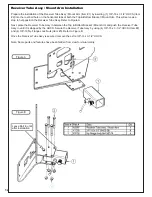
Page 27: ...27 A2207 Mount Arm Tube Assembly...

Page 28: ...Part Desc Qty 1 B0958_02 Idler Mnt Pl 1 2 K2038 Ny Flange Lock Nut 3 8 16 2 3 K1463 Flat Washer 720 ID x 1 500 OD x 250 T 2 4 K1219 Jam Nut 3 8 16 1 5 K1192 HHCS 3 8 16 x 1 1 4 GR5 1 6 K0329 Nylock Nu...

Page 29: ...Gearbox 1 2 K0428 HHCS 5 16 24 x 1 GR8 1 3 K0043 Lock Washer 5 16 1 4 N0002 Pillow Block Bearing 7 8 1 5 K0035 Set Screw 5 16 18 x 1 4 Cup Point 1 6 J0272 Woodruff Key 9 1 7 A2048 Clutch Flange Assy...

Page 30: ...nted Washer 7 16 1 375 OD x 440 ID x 179 T 1 4 K0140 Lock Washer 7 16 High Collar Helical Spring 1 5 K0359 HHCS 7 16 20 x 4 00 w Patch 1 6 M0309 A Section Pulley 4 75 OD 1 7 S0221 Eng Pulley Bushing 2...

Page 31: ...31 Item Part Desc Qty 1 K0048 Lock Washer 3 8 4 2 K0343 HHCS 3 8 16 x 7 8 GR8 4 3 A2059_01 Clutch Sub Assy 1 4 A2058 Gearbox Sub Assy 1 A2057_01 Drive Assembly Exploded Parts View...

Page 32: ...32 A2060_01 Mounted Drive Assembly...

Page 33: ...7 K0353 HWHTCS 1 4 20 x 1 2 2 8 K1154 HHCS 5 16 18 x 1 4 9 K2516 Ny Flange Lock Nut 5 16 18 2 10 A2060_01 Mounted Drive Assy 1 11 P0271 Quick Connect Wire Harness 1 12 K1142 5 16 18 x 3 4 Carraige Bol...

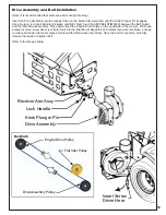
Page 34: ...34 A2061_02 Drive Assembly 4 Blade Impeller...

Page 35: ...35 9 7 19 11 3 3 2 10 1 14 4 12 15 16 18 17 5 6 13 8 20 21 22 22 23 24 24 25 26 26 27 28 A2100 6512 Box Assembly Exploded Parts View...

Page 36: ...rt Desc Qty 1 B1000 Latch Rod Hook Side 1 2 K0400 1 2 Flat Washer 1 084 OD x 528 ID x 120 T 2 3 J0303 Spring 1 4 K0086 Hair Pin Clip 125 OD x 2 50 1 5 A2106 Latch Rod Weldment 1 A2107 Latch Rod Assemb...

Page 37: ...37...

Page 38: ...cal Service Center for replacement decals Part R1054 Important Hose Wear Part R1051 Warning Hearing Protection Part R1069 Warning Turn Off Blower Part R2007 Danger Never Use Hands Part R2008 Danger Ro...

Page 39: ...of leaves whether the Experts recommend not cutting off more than 1 3 of terrain is flat or hilly etc Wet grass and leaves will decrease effectiveness and Remember that horsepower requirements will v...

Page 40: ..._____________ Unit Model Number _______________________________________________ Address _________________________________ State _______ Zip _______ New PECO Inc Phone 1 800 438 5823 828 684 1234 Email...

Page 41: ...41...

Page 42: ...e speed Grass is too long Grass is too wet Worn belt Ground speed is too fast Collection bags are too full Loose belt Cut grass when it is dry Cut the grass several times Dump more frequently Always o...

Page 43: ...43 Notes...

Page 44: ...CO PECO PECO PECO PECO PECO P P P P P P P P PECO PECO R R R New PECO Inc Phone 1 800 438 5823 828 684 1234 Email peco lawnvac com 10 Walden Dr Arden North Carolina 28704 Fax 828 684 0858 Website www l...

Reviews: