


22
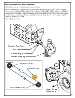
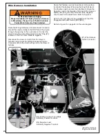
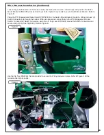
Wire Harness Installation
Disconnect the mower’s clutch from the mower’s
harness and connect the Wiring Harnesses’ Engine
Connector (#2) to the clutch wiring and to the mower’s
harness.
Route the Wiring Harnesses’ Female Quick Connector
around the engine, between the ROPS and the engine
through the opening in the rear bumper. Connect the
Quick Connector to the Male Quick Connect Plug (#1)
located on the PTO Drive.
Refer to Figure A.
Refer to Figure D on page 24 for the wire diagram.
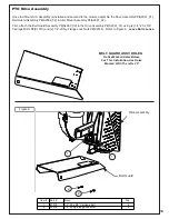
Refer to the next page for the installation of the PTO
Engagement Rocker Switch (P#P0293).
Route the Positive Lead w/ Fuse Block to the positive
terminal of the battery (#3) using the Ring Terminal of
the Positive Lead to secure the attachment. Route the
Negative Lead to the Negative Terminal of the mower’s
battery (#4) using the Ring Terminal of the Negative
Lead to secure the attachment. Refer to Figure A.
(#3) Positive Lead w/ Fuse Block
to Battery Positive Terminal
(#4) Negative Lead
to Battery Negative Terminal
WARNING
!
To Prevent Serious Injury-
Proper Installation Of Safety Interlock Harness
Is Mandatory. Please Check That All Interlock
Points Work Correctly Once Installed.
Figure A
(#1) Wire Harness
Quick Connector
(#2) Wire Harness
Engine Connector
Summary of Contents for 23651201
Page 24: ...24 Wire Harness Installation Continued Figure D...
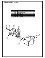
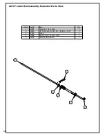
Page 27: ...27 A2207 Mount Arm Tube Assembly...
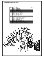
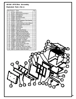
Page 32: ...32 A2060_01 Mounted Drive Assembly...
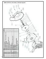
Page 34: ...34 A2061_02 Drive Assembly 4 Blade Impeller...
Page 37: ...37...
Page 41: ...41...
Page 43: ...43 Notes...