


はじめてサウンドシステムの電源を入れるときは、最初にアップストリームの電気系統をすべてオンにし、次に
PVXp 12
を、その
レベルコントロールを反時計回りに
(
最後まで
)
回し切ってオンにします。ミキサー出力レベルコントロールを下げ切った状態で
レベルチェックから始めます。ゆっくりレベルを上げ、
PVXp 12
レベルコントロールを目的の設定にします
(
はじめは
3
分の
1
のとこ
ろまでセットすることをおすすめします
)
。
PVXp 12
のレベルコントロールを上げ切り、次にミキサーからのみレベルを調節しようとするのはおすすめできません。過度のノ
イズを引き起こす傾向があります。ベストな方法は、ミキサーからケーブルを通して
"
ホット
"
な信号を
PVXp 12
に送り、次に
PVXp 12
レベルコントロールを、必要なフル出力に達するのに必要なだけ上げることです。この方法では、ミキサー出力がクリ
ッピングしていないことを確認する必要があります。
PVXP 12
から
AC
電源を遮断
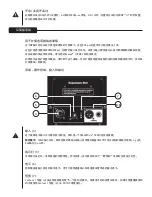
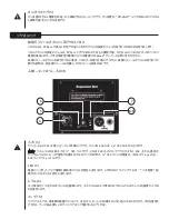
最初に電源スイッチ
(3)
を使用して本体ユニットをオフにしてから、
AC
電源コードを取り外すことをおすすめします。これは、電
源を切る間にパワーアンプやトランスデューサにかかる応力を最小にするためです。電源スイッチには、ターンオフ時に役立つア
ーク抑制コンデンサがあり、
AC
電源からの切断をクリーンにする働きがあります。電源コードの
IEC
コネクタは、コードが小刻み
に動くときなど、最終的に完全に切断される前に断続的に接触することがあります。
トラブルシューティング
出力がない
最初に、本体ユニットに
AC
電源が来ていてオンになっているか確認します。パワーアンプモジュールの
LED
が点灯しているこ
とを確認します。
緑色に点灯していない場合、オン
/
オフスイッチ
(3)
がオン位置か確認し、
IEC
電源コード
(2)
がしっかり安定して接続されて
いるか確認します。
AC
電源コードが
AC
コンセントに差し込まれているか確認します。最後にブレーカー
(1)
をチェックします。
(
安全上の注意事項については「リアパネル
:
ブレーカー」のセクションをご覧ください。
)
本体に
AC
電源が来ていることを確認した後、
PVXp 12
が信号を受けているか確認します。入力につながるケーブルを一時
的に外し、信号を再生できる他のデバイス
(
パワーアンプやスピーカー
)
に接続します。これで信号が再生される場合、使用さ
れているすべてのレベルコントロールが満足のいくレベルまで上がっている
(3
分の
1
ないし
2
分の
1)
か確認します。
PVXp 12
に直射日光や過剰な熱の影響を受けている場合、内部のサーマルプロテクトが起動していることも考えられます。
その場合は、
PVXp 12
の電源を切り、温度が下がるまでしばらく放置します。
それでも出力がない場合は
Peavey
®
ディーラーまたは
Peavey
サービスセンターまでお問い合わせください。
ハム、ノイズ
PVXp 12
にハムあるいはノイズがある場合、これは
AC
コンセントに関係します。
PVXp 12
を別の
AC
コンセントに接続してみま
す。ミキサーや
PVXp 12
に別の回路
(
ブレーカー
)
を使用する場合、ハムの問題が起こることもあります。現実的でない場合を
除いて、同じ壁コンセント
(
ブレーカー
)
からミキサーとパワースピーカー両方に電源を供給するのがベストです。
信号を
PVXp 12
の入力に送るためシールドケーブルが使われていることを確認します。シールドケーブルではなく、
1/4"
プラグ
のスピーカーケーブルを使用する場合、これはハムあるいはノイズの原因になります。
ハムはグランドループに関係することもあります。
PVXp 12
側の平衡ケーブルでシールドグランド
(
ピン
#1)
をリフトするのも役立
つことがあります。ケーブルの取り付け、取り外しの前あるいはスピーカー側でシールドグランドをリフトする前には、まず最初に
レベルコントロールを下げて入力の変化をよく確認してください。
PVXp
™
12
、ミキサー、または任意のソースデバイスと同じ回路に調光器(照明調節スイッチ)がないことを確認します。調光
器が使われている場合は、これを完全オンまたは完全オフにすることでハムがなくなるか少なくなることがあります。これは典型
的な
AC
配線
/
調光器の問題であり、
PVXp 12
の設計の問題ではありません。
AC
プラグの
3
番目のワイヤ
(
グランドプラグ
)
は決して取り外さないでください。安全上の問題を引き起こす原因になります。
音が歪む、不鮮明
最初にミキサー
(
信号ソース
)
がクリッピングやオーバードライブになっていないことを確認します。
PVXp 12
でレベルコントロール
(6)
の設定が低すぎないことを確認します。
PVXp 12
リアパネルの入力ジャックに入力プラグがきちんと収まっているか確認しま
す。
PVXp 12
の入力ジャックにパワーアンプの出力がつながっていないことを確認します。延長コードを使用して
AC
電源を本
体ユニットに供給している場合、電流容量は十分かどうか、また、他のデバイスにも電源を供給するために使用していないこ
とを確認します。
Summary of Contents for PVXp 12
Page 1: ...www peavey com PVXp 12 Two Way Bi Amped Sound Reinforcement Enclosure Operating Manual...
Page 4: ...KOREAN ARABIC CHINESE JAPANESE...
Page 92: ......
Page 93: ......
Page 96: ......


