


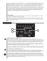


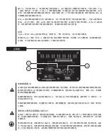


JACk THRU (8 & 9)
Questi jack sono destinati al collegamento in serie di più unità PVXp
™
12 o per fornire segnale a un subwoofer attivo o altri
circuiti che richiedano una versione full range del segnale di ingresso. I connettori disponibili sono un jack maschio XLR (8)
e un jack TRS da 1/4” (9).
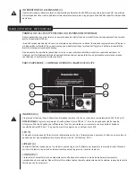
ATTENZIONE:
L'unità deve essere scollegata dalla fonte di alimentazione a corrente alternata prima di svolgere qualsiasi tipo di lavoro
su di essa. Segnalare tutti gli interventi di manutenzione al personale di assistenza qualificato.
La piastra posteriore può raggiungere temperature elevate. Non bloccare o coprire la ventola o le alette di scarico
ostruendone la ventilazione. Lasciare uno spazio libero minimo di 4 pollici dietro la ventola. Non ostruire il flusso d'aria con
oggetti come tende o drappi, materiale isolante termico per costruzione, ecc. Si raccomanda inoltre di non posizionare il
retro del PVXp 12 in spazi chiusi o privi di ventilazione.
Assicurarsi di tenere il microfono lontano dalla parte anteriore del diffusore dopo averlo collegato all'ingresso e durante la
regolazione del volume del microfono, o si rischia di produrre un feedback a volume molto alto! Se ciò accade potrebbero
verificarsi guasti al sistema!
NON collegare le uscite di amplificatori di potenza agli ingressi dell'unità PVXp 12. Gli ingressi sono studiati per segnali di
livello di linea.
NON rimuovere le griglie metalliche di protezione.
ATTENZIONE! L'unità PVXp 12 è molto efficiente e potente! Questo diffusore sonoro può causare danni permanenti
all'udito! Prestare particolare attenzione alla regolazione del volume massimo generale!
L'apparente livello sonoro dell'unità PVXp 12 potrebbe trarre in inganno a causa della chiarezza e nitidezza del suono in
uscita. La mancanza di distorsione o di evidente affanno dell'apparecchiatura potrebbe far apparire il livello sonoro molto
più basso rispetto al valore effettivo. Questo sistema è in grado di produrre livelli di pressione sonora superiori a 127 dB a
distanza di 1 m dal diffusore!
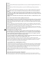
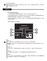
SOSPENSIONE DEL PVXP 12
INFORMAZIONI DI SICUREZZA IMPORTANTI PER IL MONTAGGIO E LA SOSPENSIONE DEL PEAVEY PVXp 12
ATTENZIONE: prima di procedere al montaggio sospeso di questo modello di diffusore si prega di consultare un tecnico
qualificato esperto di strutture. Il diffusore potrebbe cadere a causa di una sospensione impropria, con eventuali
conseguenti gravi infortuni e danni all'immobile. NON sospendere altre casse al di sotto della prima, né appendere
ulteriori pesi alla stessa. Utilizzare solamente i corretti utensili abbinati. La responsabilità per la sistemazione
dell'impalcatura è esclusivamente di altri.
L'angolazione massima delle casse sospese è di 30°.
Utilizzare sempre una catena di sicurezza adeguata o una fune, fissata a un gruppo non utilizzato di punti di sospensione
o al cabinet come indicato da un tecnico qualificato esperto di strutture, e fissata saldamente ad un elemento strutturale
adatto, seguendo le indicazioni di un tecnico qualificato esperto di strutture.
L'intervallo raccomandato di momento torcente per i bulloni di montaggio è di 3,5-4,0 piedi-libbre (4,75-5,42 Nm)
EVITARE DI
STRINGERE ECCESSIVAMENTE I BULLONI!
Se un inserto gira a vuoto, è danneggiato, e il cabinet non può essere sospeso in modo
sicuro da tale set di inserti!
Non trasportare il diffusore mentre montato su staffe in serie o altri supporti in quanto questo potrebbe causare stress
eccessivo negli inserti di montaggio.
L'uso di frenafiletti (tipo blu/forza media) sui bulloni di montaggio è raccomandato, in quanto sono le rondelle di blocco
appropriate, ad assicurare che l'attrezzatura di montaggio non vibrerà con il tempo.
GRUPPI DI SET DI INSERTI
Gruppo A
Un set di due inserti M10 sulla parte superiore progettato per sospendere il cabinet usando idonee viti a occhielli.
Gruppo B
Un set di due inserti M10 sulla parte bassa progettato per sospendere il cabinet usando idonee viti a occhielli.
I S T R U Z I O N I P E R L ' U S O
Summary of Contents for PVXp 12
Page 1: ...www peavey com PVXp 12 Two Way Bi Amped Sound Reinforcement Enclosure Operating Manual...
Page 4: ...KOREAN ARABIC CHINESE JAPANESE...
Page 92: ......
Page 93: ......
Page 96: ......


