22
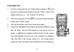
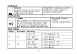
Continuity Test
1. Turn the rotary switch to the measurement function “
” and
select the continuity test function with the "FUNC." button. The
display will show “
”, “OL” and the “
W
” symbol.
2. Insert the red probe in the “
” socket and insert the black
probe in the “COM” socket.
3. Connect the probes’ tips to the measuring object.
4. The buzzer will signal if continuity is present (resistance is less
than 30 ±5
W
.) and the LED-indicator of the device will turn
green. In addition the resistance will be shown on the screen.
The LED-indicator will turn red, if the resistance is between
30
W
and 50
W
. If the screen shows “OL”, the measurement
range has been exceeded or the measuring circuit is defective.
Summary of Contents for PCW02A
Page 1: ...1 User Manual PCW02A Digital Multimeter...
Page 2: ...2...
Page 3: ...3 English 4 Deutsch 42 Fran ais 81 Portugu s 119 Italiano 157...
Page 195: ...195...


