


Chapter 4— LED Indicators
To program this configuration into the device we press the “Program
Device” button. UPStart performs the necessary command steps to program
the configuration data into our device. When the command steps are
complete we can press the OK button to close the dialog.
Configuring LED Group Behavior
As explained before, the LED indicators behind each pushbutton light up
whenever certain events occur. Sometimes it is useful to have another LED
or group of LEDs configured to turn on or off at the same time as one LED
turns on. For example, when you want the LEDs to indicate which scene is
currently active in a room you will want all of the other LED to extinguish
when the LED associated with the current scene lights up. Another
example is when you want to use the ON and OFF Buttons to turn all lights
on and off while you use the ‘A’, ‘B’, ‘C’, and ‘D’ Buttons to control
individual lights.
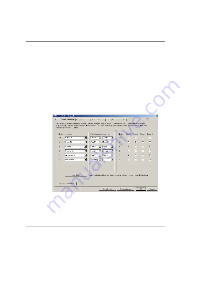
PCS 6-Button Controllers allow each LED indicator to be part of any of 4
different LED Groups. To configure which LED Groups contain which
LED indicators we again go to the Receive Components tab of the Edit
Device dialog.
Each LED Group has a checkbox for each LED Indicator. To put an LED
into an LED Group simply check the box that corresponds to that LED in
that group.
The UPB 6-Button Controller User’s Guide
31


