Page 69
Ph: 804.227.3023
10511 Old Ridge Rd. Ashland, VA 23005
4LHD/4LHDX Application Manual
Powertrain Control Solutions
REV 1.1
TPS Verification Checklist
You must be able to answer YES to all of these statements to verify proper sensor installation.
1. The sensor is mounted in a location that is free from excessive vibration, protected from heat sources,
debris, and fluids.
2. The sensor is mounted with proper fasteners (lock washers, lock nuts, etc) and uses appropriate
materials (no uncoated steel, etc) for the sensor to last the anticipated life of the vehicle.
3. When the accelerator pedal is at idle (not depressed), the sensor arm is off of the minimum stop and
the voltage as shown on the TCM software monitor screen is between 0.5V and 1.5V.
4. When the sensor arm is disconnected from the linkage that connects it to the engine or pedal, the
sensor arm returns to the minimum stop and the voltage on the TCM software monitor screen is below 0.2V. Code 22
becomes active after three seconds.
5. When the pedal is pressed, the sensor arm moves accordingly. There is no movement or “slop” such
that the pedal or engine throttle blade can move without seeing a voltage change on the TCM software monitor screen.
6. The sensor moves freely without binding. The sensor does not provide any resistance or change to
the operation of the throttle linkage.
7. When the accelerator pedal is at full throttle, the sensor arm does not contact the maximum stop and
the voltage as shown on the TCM software monitor screen is between 3.5V and 4.5V.
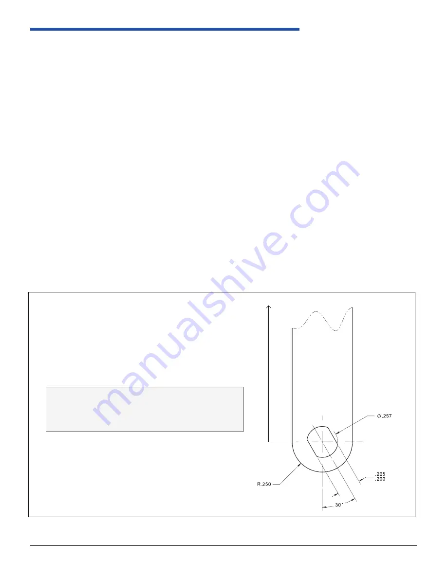
It is strongly recommended to use the arm provided by
PCS. In situations where the vehicle manufacturer must
design a custom arm, refer to figure 2.6.8.12-3 provided
for the design of the arm to the sensor.
Minimum length: 1.5” (so arm contacts stops)
Figure 2.6-3: Shift Arm Specifications


