PCME QAL 181 X User Manual Download Page 94


- PCME QAL 181 MANUAL: 94 - 

13


 CLEANING PROCEDURES 

 
The are several controls both at the control unit and within the sensor enclosure to aid the 
following cleaning procedures. 
 

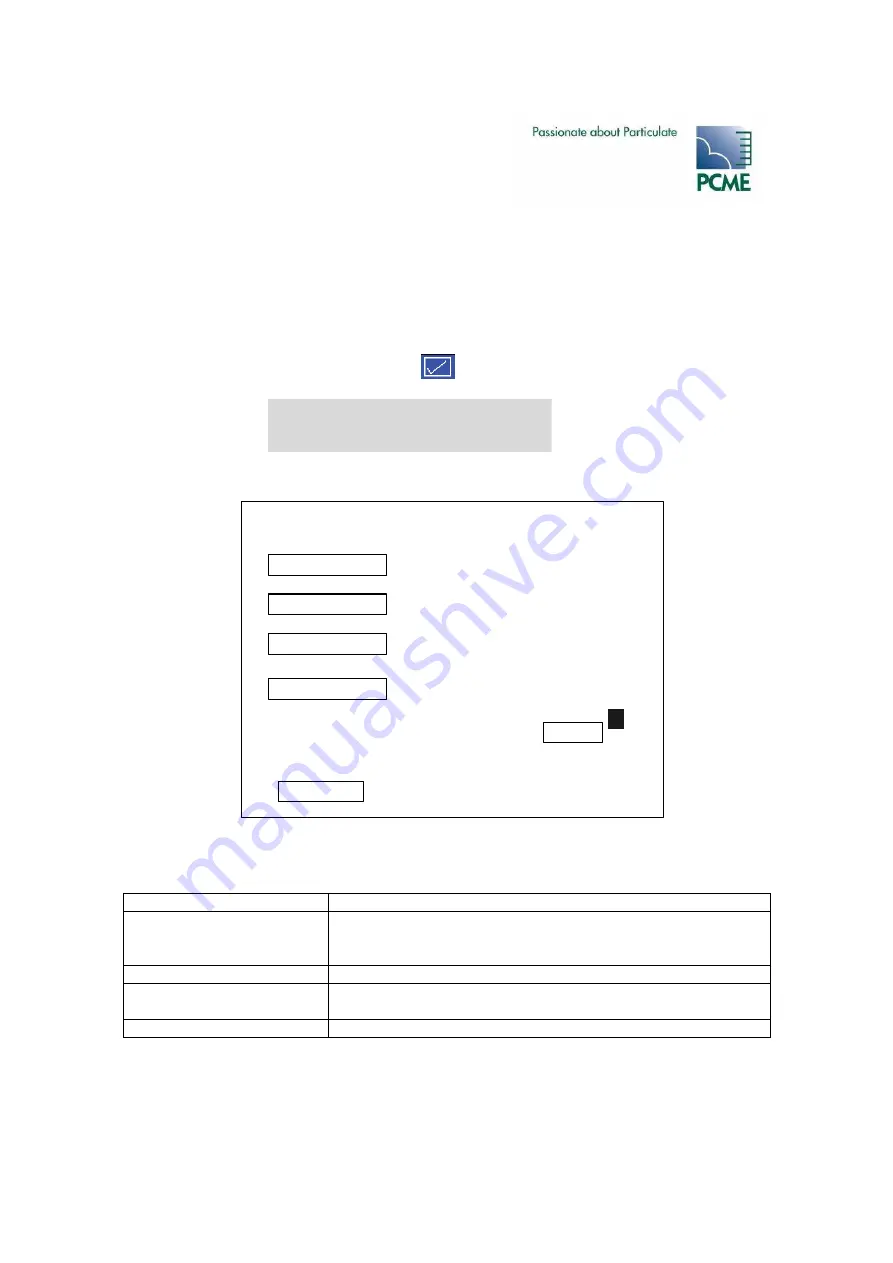
The Cleaning Screen in the Control Unit 
 

Select ‘Quality Assurance/Self Tests’ display  


Select Device = 181 Dust channel 
Select “Cleaning” 


The Cleaning Screen is displayed: 


The Cleaning Screen provides user control of the sensor: 


Entry Shutter 

Place the quadrant into the shutter position. This should be done 
before attempting to cleaning the measurement region to stop 
dust entering the sensor. 

Exit Shutter 

This function is not used. 

Span Element 

This places the quadrant into the Span Test position. This makes 
the span test element visible to aid cleaning of the span element. 

Laser 

Turns laser off to provide safety whist cleaning. 

 
The Quadrant Position setting adjusts the position of the quadrant. This should not normally be 
adjusted. 

Cleaning

Exit

Entry Shutter

5.5

>

>

Activate

Activate

Activate

Activate

Exit Shutter

Span Element

Laser

Quadrant Position

Open / Closed

Open / Closed

Open / Closed

30

Purge Flow

On / Off

Summary of Contents for QAL 181 X

Page 1: ...ocumentation These should be forwarded to the Technical Department at the address given below This manual is intended as a guide to the use and installation of the product and therefore PCME Ltd shall...

Page 2: ...PCME QAL 181 MANUAL 2...

Page 3: ...INSTALLATION OVERVIEW 16 3 4 MEASUREMENT COVER REMOVAL 18 3 5 SENSOR TUBE ORIENTATION 19 3 6 INSERTION DISTANCE 20 3 7 FLANGE MOUNTING 21 3 8 SUPPLYING INSTRUMENT AIR 23 3 9 MOUNTING THE BLOWER UNIT O...

Page 4: ...ctions 48 Power Supply Connections 49 6 INITIAL SET UP 50 6 1 INTRODUCTION 50 6 2 POWER UP 50 6 3 CHECKING THE COMMUNICATIONS MODE 50 6 4 AUTODETECT SENSORS 51 6 5 EDITING BASIC SENSOR SETTINGS 52 6 6...

Page 5: ...ulating the Calibration Factor Manual Method 82 Calculating the Calibration Factor Automatic Method 82 11 TROUBLESHOOTING 84 11 1 COMMUNICATION FAILURE 84 11 2 DIAGNOSTICS 84 11 3 CHECKING SPURS 84 11...

Page 6: ...BE SERVICED BY PCME OR ITS DESIGNATED REPRESENTATIVE PCME is an EN ISO 9001 accredited design and manufacturing organisation and within the limits specified in this manual manufactures instruments whi...

Page 7: ...way a hazard to health Particulate contained within high temperature gas Unless the process conditions are known to be entirely safe suitable precautions such as the use of breathing apparatus or duct...

Page 8: ...Stack diameters 250mm 3m Sensor Specification Enclosure temperature rating 25 C to 55 C Stack temperature rating 25 C to 250 C option to 500 C Enclosure rating IP 65 Enclosure material Die cast alumi...

Page 9: ...sensor 0 250 C 0 500 C Insertion length The insertion length can be adjusted from 15mm to 600mm by adjusting the flange position ATEX IECEx Category options ATEX Category 3 gas Zone 02 Category 2 dus...

Page 10: ...entries Capacity stated for 4 sensors plus QAL3 channels 2 months 15 minutes 7 days 1 minute 2 hour 1 second 500 entries Ethernet enabled option None Ethernet Modbus TCP optional Outputs 1 x RS 485 M...

Page 11: ...PCME QAL 181 MANUAL 11 Analogue output module AOM 8 x 4 20mA 500 Ohm Alarm output module ROM 8 x Relay 1A 250V Isolating Spur Provides Surge protection...

Page 12: ...0125X Sira 10ATEX4260X Certification code Ex nA IIC T4 Gc Ex tb IIIC T63 C Db IP66 Ta 20 C to 55 C Ex tb IIIC T63 C Db IP66 The following special conditions apply i The electronics enclosure is certi...

Page 13: ...or sealing then it is the responsibility of the user to take suitable precautions that prevent it from being adversely affected thus ensuring that the type of protection notably IP66 ingress protectio...

Page 14: ...into the duct for installation or maintenance purposes If in doubt consult the local Safety Officer and or local Safety procedures Probe Damage Take care when handling the sensor to avoid damaging the...

Page 15: ...PCME QAL 181 MANUAL 15...

Page 16: ...on relative to sampling ports and obstructions Orientation of sensor Provide orientation details to PCME on the site survey form at time of order horizontal or vertical stack Prepare flange mounting f...

Page 17: ...Probe into flange mounting Remove cover from measurement volume see picture above Ensure air purge blower or instrument air is connected and running before insertion Additional optional setup Add othe...

Page 18: ...ting sensor into the stack This is essential for the measurement to work and allow the air purge to work correctly 5 1 3 4 2 6 To remove the measurement cover Remove the screws 1 from the end cap Alle...

Page 19: ...irement the Inner Tube must not obstruct the direction of flow the enclosure must be installed with the cable glands and air purge entry pointing downwards On the site survey form specify one of the f...

Page 20: ...t least 150mm from the stack wall to avoid the boundary layer The PCME QAL 181 is provided with a single length probe However the flange position is site adjustable to suit the installation details st...

Page 21: ...E QAL 181 is supplied with a flange with 2 sets of bolt holes Note Option B provides near compatibility for use with PN6 DN80 with 12mm bolts Pitch circle Hole size OD Option A DN80 PN10 PN16 160mm 18...

Page 22: ...ize 110mm IMPORTANT Weld the flange mounting tube so the angle of installation is horizontal or pointing slightly downward e g 5 to allow condensate to drain off On horizontal ducts do not install the...

Page 23: ...sure Regulation and Primary Filtration Filter for Primary Particle Filtration 0 1 m Filter for Secondary Particle Filtration 0 01 m Oil Vapour Removal 0 1mg m3 ANR saturated 0 001mg m3 before saturati...

Page 24: ...Pressure AIR IN 2 to 10 Barg Outlet Air Pressure Guage 200 to 300 mbarg Pre Filter Nominal Filtration Rating for Particulate 5um Additional Filtration Rating for Particulate 0 01um Oil Vapour 0 001 mg...

Page 25: ...e opening enclosure Positive stack pressure will reduce the air purge capability With zero stack pressure blower delivers 50 Litres minute Above 15mbar positive stack pressure it is recommended to use...

Page 26: ...PCME QAL 181 MANUAL 26 5 4 2 1 3...

Page 27: ...attach to the sensor The blower enclosure is designed to be wall mounted with the air and power connections pointing downwards Feet are supplied to aid mounting The blower unit requires a mains power...

Page 28: ...outer sheath outside diameter 7 9mm Colour coding power black 0v brown 24 Vdc Colour coding comms green A blue B Network Layout Connect multiple sensors to the control unit either by daisy chaining or...

Page 29: ...ME QAL 181 MANUAL 29 4 core Power 24V DC Comms RS485 115 230V AC Figure 3 1 Standard System 115 230V AC 4 core Power 24V DC Comms RS485 4 core Power 24V DC Comms RS485 Figure 3 2 PLUS System Spur Link...

Page 30: ...PCME QAL 181 MANUAL 30 Figure 3 3 PLUS System Daisy Chained...

Page 31: ...sor Wiring 1 BUS IN and BUS OUT connectors 4 Laser 2 M20 cable glands 5 Servo motor for span test 3 Air purge connector M10 6 Receiver 7 PT1000 temperature sensor Ensure the cabling is not connected t...

Page 32: ...US IN terminals Make the connections to the BUS IN terminals as follows from left to right BUS IN TERMINAL Connect the next Sensor in the network to the BUS OUT terminals Route the cable through the c...

Page 33: ...talled in enclosure lid Service Buttons from top to bottom A Entry Shutter Open Close B Exit Shutter Open Close not used C Span Element Open Close D Laser On Off 1 PCB Safety cover 2 Service Buttons 3...

Page 34: ...nsure the cable sheath penetrates the Sensor Unit entry gland Fit blanking plugs to unused cable entry glands Ensure cable entry glands are tightened to the cable Support cables at appropriate interva...

Page 35: ...For example to set address number 5 Set switch 1 binary 1 ON and switch 3 binary 4 ON 4 1 5 Communication Settings SW101 The sensor has two comms settings ASCII and RTU The default setting is ASCII 19...

Page 36: ...G THE FRONT COVER HAZARDOUS VOLTAGES A SUITABLE APPROVED AND RATED ALL POLE DISCONNECT DEVICE MUST BE INSTALLED IN THE BUILDING INSTALLATION IN A READILY ACCESSIBLE POINT NEAR THE CONTROLLER THE CONTA...

Page 37: ...Height 110 mm the mounting holes are elliptical to allow flexibility of position Data Cabling Specification Data cabling for the MultiController provided by PCME meets the following specification 2 pa...

Page 38: ...should be provided If the unit is located in an area which is accessible to unauthorised personnel it is recommended that access to the unit be restricted by some form of lockable cabinet 4 4 Compone...

Page 39: ...als PL6 8 Data Bus Sensor Network PL1 3 Alarm contacts terminals PL5 9 Bus termination switch SW200 4 Isolated 4 20mA outputs PL4 10 Data Bus Sensor Network PL7 5 Digital inputs terminals PL3 11 Fixin...

Page 40: ...e Connection Data cable connections are as follows from left to right SENSOR NETWORK CONNECTORS PL1 PL7 Installing the MultiController at the end of a network Route the data cable through the cable gl...

Page 41: ...ed RS232 485 port for connection to a PC PLC Route a suitable cable through a vacant cable gland and connect to PL2 as shown The maximum cable length for RS232 is 25 metres The maximum cable length fo...

Page 42: ...ct to PL4 as shown Alarm Contact Connections PL5 The MultiController is fitted with four voltage free SPCO with a 2A current rating The relays can be used to switch mains voltages The maximum current...

Page 43: ...tain a power disconnect device An easily accessible external disconnect device and fuse must be fitted in the power supply wiring The disconnect device must have a contact separation of not less than...

Page 44: ...HE FRONT COVER HAZARDOUS VOLTAGES A SUITABLE APPROVED AND RATED ALL POLE DISCONNECT DEVICE MUST BE INSTALLED IN THE BUILDING INSTALLATION IN A READILY ACCESSIBLE POINT NEAR THE CONTROLLER THE CONTACT...

Page 45: ...7 9mm Colour coding power black 0v brown 24 Vdc Colour coding comms green A blue B Power Supply Cabling Specification For mains connections use appropriate cable with conductor area in range 0 75mm2 t...

Page 46: ...Module Connections 1 Mains fuse 1Amp 7 Earth stud cable screen 2 off 2 Mains supply terminals 8 RS232 RS485 terminals 3 Alarm contacts terminals 9 Data Bus Sensor Network Connector 4 24V input 10 Fix...

Page 47: ...ble fl at vertical surface Data Cable Connection Data cable connections are as follows from left to right SENSOR NETWORK CONNECTOR Route the data cable through the cable gland nearest to the SENSOR NE...

Page 48: ...wn The connection should be made between the required input and common ground 4 20mA Output Connections The Interface Module is fitted with one isolated 4 20 mA outputs each capable of driving a 250 O...

Page 49: ...QUIPMENT MUST BE EARTHED All electrical wiring must be carried out in accordance with local regulations The unit does not contain a power disconnect device An easily accessible external disconnect dev...

Page 50: ...splay illuminates The icon bar is shown as follows The required display is selected using the cursor and enter keys Selects Multiple Devices display Selects Bar Graph display Selects System Overview d...

Page 51: ...unctions Sensor Comms Mode The settings should be as follows Setting Mode Baud Rate Parity Standard ASCII 19200 Odd Optional RTU 19200 None If problems are encountered communicating with a sensor chec...

Page 52: ...Device 990 Address 2 Device 990 Address 3 Device AOM Autodetect Sensor Setup Time Date 4 20mA Settings Relay Settings Log Rates More Settings Other Functions System Setup www pcme co u k 7 01 Figure 5...

Page 53: ...g x Calibration Factor The Calibration Factor is applied to The Bar Graph Text display values used to generate emission alarms Logged data within the instrument Analogue 4 20mA Outputs Modbus RS485 Ou...

Page 54: ...Instant Alarms or Average Alarms Instant alarms Instant alarms use the pulse reading read from the sensor usually once every second Instant alarms should only be used if quick detection of a sudden ch...

Page 55: ...ration Changing the time date may result in loss of logged data The system does not automatically change the time for daylight saving hours clocks forward or back Default setting is Greenwich Mean Tim...

Page 56: ...utputs have the following specification Isolated outputs Maximum loading 500 Ohms Update rate 1 second Scaling and Filtering 4 20mA Outputs Select Setup display Menu route 4 20mA Settings The followin...

Page 57: ...4 25 50 20 4 4 8 12mA If Stack3 Dust 25mg m3 then Output 2 4 25 20 40 20 20 4 4 4 8mA Testing and Calibrating 4 20mA Outputs The 4 20mA outputs can be tested for correct output current Select Setup d...

Page 58: ...4 20mA output channel as required Select Back to return to the main menu Analogue Output Modules The Control Unit has a limited number of 4 20mA outputs Multicontroller 4 Interface Module 1 Therefore...

Page 59: ...display Select Device Output AOM Figure 5 7 AOM 4 20mA Output Testing Zero 1 2 3 Stack5 Dust Stack6 Dust Stack7 Dust Back Device Span Filter secs 4 Stack8 Dust 0 000 100 0 0001 0 000 0 000 0 000 100...

Page 60: ...the AOM The screen displays the current mA level of each of the 8 outputs An output can be temporarily forced to either 4mA or 20mA by selecting the relevant test button next to the output To return...

Page 61: ...g caused by faulty wiring to the sensor Relay 2 Limit Alarm from any channel sensor either instantaneous or average Relay 3 Warning Alarm from any channel sensor either instantaneous or average Relay...

Page 62: ...for alarms to stay latched after the end of an alarm condition use the Latch Alarm function Select Setup display Menu route Other Functions Latch Alarms The relays can be put in a failsafe mode In th...

Page 63: ...by automatically or manually To add ROMs automatically Select Setup display Menu route Autodetect To add ROMs manually Select Setup display Menu route More Sensors Add a new device ROM Relay Output M...

Page 64: ...an be put in a failsafe mode In this mode during normal non alarm conditions the relays are energised and de energised when an alarm is generated In the event of a power failure of a power loss to the...

Page 65: ...Device Output Relay The following screen will be displayed The Comms Check tests the communication with the ROM The screen displays the current state of each relay The status of each relay can also b...

Page 66: ...e following intervals 1 2 5 10 15 30 60 120 240 minutes The short term memory may be set to log at any of the following intervals 10 15 20 30 60 120 240 seconds 6 12 More Sensor Settings The More Sett...

Page 67: ...Limit Alarm Alarm Delay s 0 000 Self Tests active Poll Rate ms Plant Run Input Clip Level Cancel 0 000 60 0 000 0 000 5 Yes 1000 No 1000 0 Save Log Options Enabled ENABLED other calibration settings o...

Page 68: ...sensor is reading correctly If the sensor fails to communicate for 10 seconds a No Response alarm will appear for that device If this happens select Edit an Existing Device and check the Modbus Addre...

Page 69: ...ings to the same value at the same time Select Setup display Menu route More Settings Edit all devices Select the parameter to be edited and set the value Select Save to apply the new settings to all...

Page 70: ...e validity of measurements Comms Check Check communication between Controller and Sensor Calibration Carry out calibration using results from Isokinectic sampling Cleaning Functions to aid cleaning of...

Page 71: ...d in raw receiver counts approximately 1 count 0 001mg m3 An alarm is generated if this result is outside 200 i e 0 2mg m3 Span Test The span test is performed by rotating a scattering device into the...

Page 72: ...reen The displayed reading is in Litres min The expected reading is 50Litres min If the reading drops below 15 Litres min a Low Purge Flow alarm is indicated in the control unit Self Test Values The f...

Page 73: ...this does not disable the Purge Flow alarm To enable disable the zero span alarms Select Setup display Menu route More Settings Edit an existing device Select device to edit Zero Span alarm Yes No To...

Page 74: ...le from software version 7 80 Comms Check Tests the communication between the controller and the selected sensor If this test fails check the wiring between the controller and the sensor Check the add...

Page 75: ...er sensors A No Response alarm will be generated in the Control Unit for that channel during the maintenance period Maintenance Mode Menu in the control unit Sensors placed in the maintenance mode wil...

Page 76: ...larms Control Unit relays and ROM devices Active Inactive Inactive Comms and Self Test Alarms Active Active Inactive 4 20mA and AOM Outputs Active Set to 0 Set to 0 Bar Graph Displays Active Active la...

Page 77: ...efurbishment if required Also messages advising inspection occur 1 month prior to Inspection due Also if the Messages are not cleared within 1 month Overdue messages will occur and the controller LED...

Page 78: ...ng agents Check the Quality Assurance Self Tests display in the controller All results should show PASS Watch the instrument performance with the process running and ensure that the process is still b...

Page 79: ...into a true dust concentration value displayed directly in mg m The use of a simple calibration factor is possible since the response of the instrument is directly proportional to the dust concentrat...

Page 80: ...age Record the sensor settings Obtain the isokinetic sampling results Test Result Calculate the New Cal Factor See Calculating the Calibration Factor above Enter the New Cal Factor Select Setup displa...

Page 81: ...e Select device to calibrate Select Calibration The following screen will be displayed Set the Start Time using the Left and Right cursor keys to change fields and the and keys to change values The Co...

Page 82: ...Calibration Factor Current Cal Factor x Test Result Sensor Average Enter the new Calibration Factor into the Controller Select Setup display Menu route More Settings Edit an existing device Select de...

Page 83: ...Duration Max Reading Sensor Average Test Result Exit Calc 17 94 5 6315 7 3200 20 04 03 10 32 00 45 D M Y h m ShortTerm Cancel Back Sensor Average Test Result Current Cal New Cal Save 5 6315 17 94 1 0...

Page 84: ...bottom of the screen A flashing red LED On the check page Quality Assurance Self Tests Comms Check No Response If the problem exists with only one or two devices visit those devices and check Cable c...

Page 85: ...he voltage at each sensor with a multimeter between the 24V and 0V pins Notes if the voltage is too low at any sensor in the network this may cause communication problems in the whole network correct...

Page 86: ...d laser caused by modulation wire disconnected laser will still be bright but receiver will not respond to it Span quadrant May come loose or servo motor may be broken result in span element or shutte...

Page 87: ...PCME QAL 181 MANUAL 87...

Page 88: ...settings press LOCK LOCK To Set Password go to System Wide Settings Autodetect Sensor Setup Time Date 4 20mA Settings Relay Settings Log rates More Settings Other Functions System Setup www pcme co uk...

Page 89: ...3 Device AOM Download Stack1 Dust 21 1 0000 0 0000 0 0000 60 0 0000 0 0000 5 Calibration Factor Instant Warning Alarm Instant Limit Alarm Averaging Time sec Average Warning Alarm Average Limit Alarm A...

Page 90: ...Delay s 0 000 Self Tests active Poll Rate ms Plant Run Input Clip Level Cancel 0 000 60 0 000 0 000 5 Yes 1000 No 1000 0 Save Log Options Enabled ENABLED other calibration settings other alarm setting...

Page 91: ...r secs 4 None Selected 0 000 100 0 0001 0 000 0 000 0 000 100 0 100 0 100 0 0001 0001 0001 Calibration AOM 1 AOM 2 Zero 1 2 3 Stack5 Dust Stack6 Dust Stack7 Dust Back Device Span Filter secs 4 Stack8...

Page 92: ...s Maintenance Mode Stop Maintenance All Devices Individual Device Maintenance Back ASCII 19200 Sensor Comms mode Baud Rate Parity Backlight off after Software Version Diagnostics Multi Cal facotrs Dig...

Page 93: ...0 04 03 10 32 00 45 D M Y h m ShortTerm Cancel Back Sensor Average Test Result Current Cal New Cal Save 5 6315 17 94 1 0000 3 1856 Save New Calibration Yes No Quality Assurance Self Tests Stack1 Dust...

Page 94: ...tter position This should be done before attempting to cleaning the measurement region to stop dust entering the sensor Exit Shutter This function is not used Span Element This places the quadrant int...

Page 95: ...Cleaning Controls in the Sensor Enclosure The same functions can be accessed directly at the sensor Unscrew the enclosure lid This reveals 4 buttons labeled A B C and D Button A Entry Shutter Open Clo...

Page 96: ...or workshops Damp or sticky contamination will require solvents or other cleaners to enable their removal using these procedures There are various levels of contamination that can occur The following...

Page 97: ...e readings have drifted from expected normal Test Self check value has dropped or reading low and the result of manual Audit Unit is also low the most likely contamination is A on the mirror of the be...

Page 98: ...then disconnect the air supply 1 5 For dry dust brush and or wipe clean the Outer Cover and the End Cap carefully brush and blow away the contamination from the baffle faces and exit cone you may nee...

Page 99: ...ffle hole so that it almost touches the span element then blow 2 3 Return the quadrant to normal position Activate Span Element Open switch on the air supply and remove the stopper 2 4 Re run span tes...

Page 100: ...ow OK with the Audit Unit re test with Span Element If the Span Element result is low carry out procedures 2 1 to 2 5 as appropriate 3 7 If both are correct but the Off Set is high and or the normal r...

Page 101: ...sed Inner Tube and refit the Beam Dump Mirror 3 14 Refit End Cap and air supply and check the Zero Span and Audit Unit readings If the Span Element Opal has become very heavily contaminated then it ma...

Page 102: ...if necessary brush and blow away the contamination including the inner surface of the Outer Tube if required 3 20 Remove the Shield Tube screws and slide the Shield Tube back Brush blow the revealed...

Page 103: ...Entry Shutter Closed Place a Shim 0 1mm if not available you can use a sheet of 80g m2 paper which is approximately 0 1mm thick between Quadrant and Inner Tube 3 25 2 Adjust as necessary loosely tigh...

Page 104: ...through the Seal in the enclosure and remove it from the Inner Tube 4 4 Block the Cross Drilling in the Inner Tube and blow out the contamination with the Air Duster may require an air line BUT ensure...

Page 105: ...along the Inner Tube and through the enclosure seal Turn the unit over and continue feeding the Quartz Rod until the locating hole is aligned with the grub screw hole in the Inner Tube Fit the grub sc...

Page 106: ...1 Introduction Minor changes to wording 2 Product Description New layout matching new range of data sheets 3 Sensor Installation Reorganise safety section Modify electrical installation to show new d...

Reviews: