5
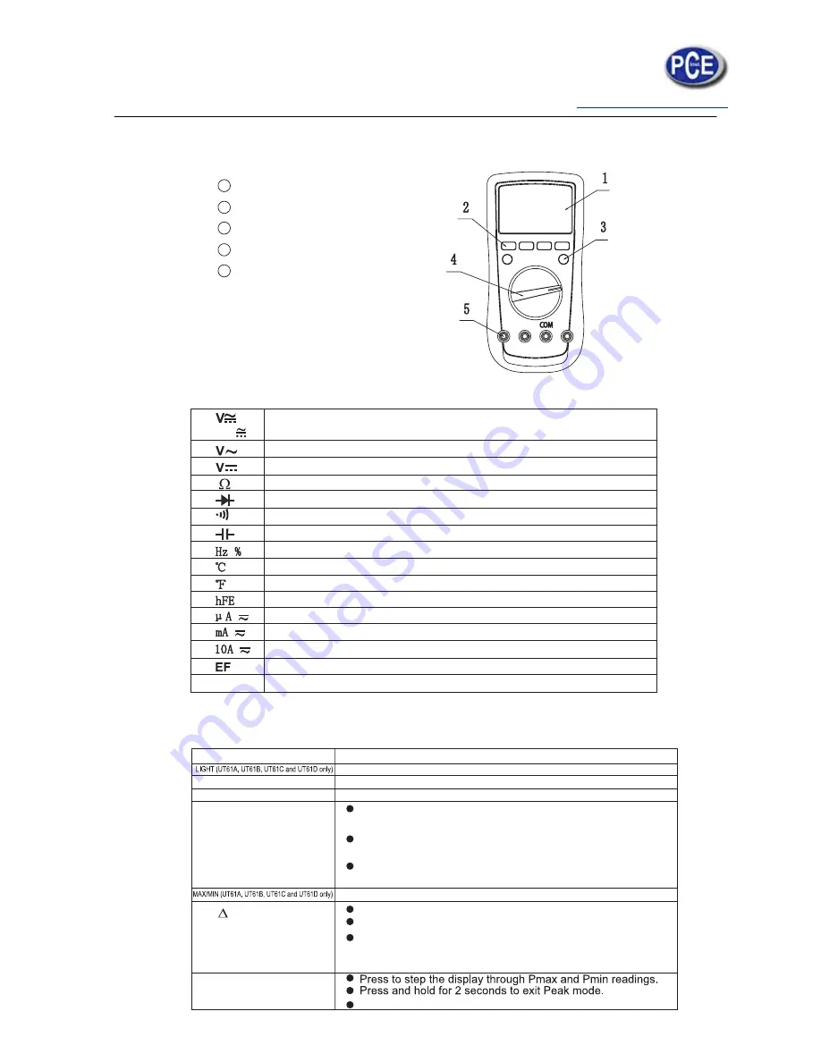
The Meter Structure
(see figure 1)
LCD Display
Functional Buttons
Blue button
Rotary Switch
Input Terminal:
1
2
3
4
5
Rotary Switch
Below table indicated for information about the rotary switch positions.
AC and DC Voltage Measurement
AC Voltage Measurement (UT61D only)
DC Voltage Measurement (UT61D only)
Resistance Measurement
Diode Test
Continuity Test
Capacitance Test
Frequency and Duty Cycle Test
Temperature in Celsius (UT61B and UT61C only)
Temperature in Fahrenheit (UT61B and UT61C only)
Transistor (UT61A only)
DCA and ACA Measurement
DCmA and ACmA Measurement
10A DC and AC Measurement
Sensor Test (UT61A only)
Power off
OFF
mV
Functional Buttons
Below table indicated for information about the functional button operations.
Press to select the maximum and minimum value.
Operation Performed
Press and hold for 2 serconds to turn the display backlight on or off.
Press to enter or exit data hold mode.
Press to select the alternate feature
Press
RANGE
to enter the manual ranging mode;
the Meter beeps.
Press
RANGE
to step through the ranges available
for the
selected function; the Meter beeps.
Press and hold
RANGE
for 2 seconds to return to autoranging;
the Meter beeps
Press again to exit REL mode
For Model UT61C, UT61C and
Press and hold for over 2 seconds to enter or exit RS232C or
USB mode.
Press to enter REL mode.
Button
Hold
BLUE Button
RANGE
REL
PEAK (UT61E only)
"CAL" means the meter enter self-calibration mode.


