background image


21 

2.9


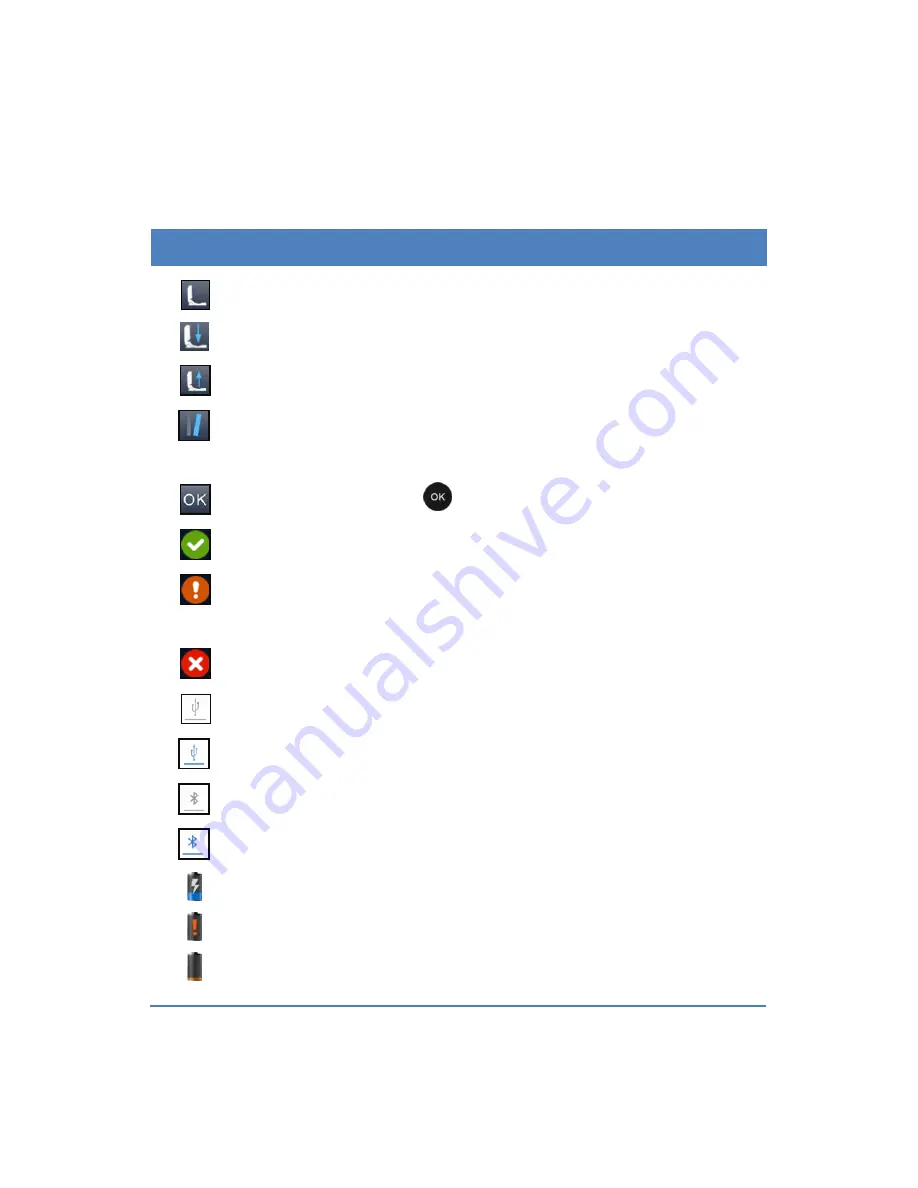
Icons and Meanings 

Table 2. 

Icon 

Meaning 


The top cover is not properly closed, close it again.


Please insert the ATP Quickswab. 


Please take out the ATP Quickswab. 


The  incline  angle  of  device  is  too  large.  (The  incline 
angle of device should be less than 30°) 


Ready, press the 

  OK >

 key to start the test. 


Pass

, test result is lower than the lower limit. 


Caution, 

test  result  is  between  the  upper  and  lower 

limit.


Fail

, test result is high than the upper limit.


USB cable is not connected. 


USB cable is connected. 


Bluetooth is not connected. 


Bluetooth is connected. 


Charging. 


Electric quantity is low. 


Electric quantity is very low, charge or power off. 

Summary of Contents for PCE-ATP 1

Page 1: ...Tel 561 320 9162 Fax 561 320 9176 info pce americas com www pce instruments com english www pce instruments com PCE Instruments UK Ltd Units 12 13 Southpoint Business Park Ensign way Hampshire Southa...

Page 2: ...hics tables data etc shall not be reproduced in any form neither print nor electronic nor translated into any other languages This manual is subject to change without prior notice The updated version...

Page 3: ...the portable ATP hygiene monitoring system in any manner unspecified in this manual may result in device damage or abnormal function Reminding Providing important information that critical to the suc...

Page 4: ...e list order Click Double click A Click or choose A on the ATP PC software Press B Press B key on the keyboard of the detector italic Bold Refers to the key button or operation instructions of the ATP...

Page 5: ...erators shall be familiar with the safety precautions and warnings described in this section before the usage of portable PCE ATP1 hygiene monitoring system 4 Non observance of the instruction provide...

Page 6: ...the usage of PCE ATP1 Quickswab Warning Do not insert any other articles into the detector except the PCE ATP1 Quickswab and do not squeeze the PCE ATP1 Quickswab while inserting Warning Please make s...

Page 7: ...ress the keys on the keyboard of detector USB Interface Precautions Icon Meaning Warning The computer that connected to the USB interface of the detector shall comply with BSEN60950 IEC950 standard De...

Page 8: ...s designed to following universality safety and EMC requirements Universality Low voltage indicator 73 23 EEC EMC indicator 89 336 EEC Safety IEC 61010 1 2010 IEC 61326 1 2013 IEC 61326 2 6 2013 IEC 6...

Page 9: ...y the requirements in section 11 of low voltage specification 73 23 EEC The design of detector also accords with the regulation that the design of electronic products should be work under specified vo...

Page 10: ...P Quickswab Structure Diagram 8 1 6 2 ATP Quickswab Operating Procedures 8 1 6 3 ATP Quickswab Storage 11 1 6 4 ATP Quickswab Safety 11 2 Basic Operation Instructions of Detector 12 2 1 Structural Dia...

Page 11: ...plate 33 3 9 Help 34 3 10 About 34 4 Test and Test Result 35 4 1 To Be Tested Interface 35 4 2 Program Selection and Setting 35 4 2 1 Selection and Setting of User defined Program Upper and Lower Limi...

Page 12: ...Chamber Clean or Replacement 46 7 Troubleshooting 47 8 Commitment Statements of After sale Services 51 8 1 Warranty Service 51 8 2 Response Time 52 8 3 Spare and Accessory Parts 52 8 4 Special Stateme...

Page 13: ...cords Export 64 11 4 User 64 11 4 1 New User 64 11 4 2 Edit User 65 11 4 3 Delete User 65 11 5 Program 65 11 5 1 New Program 66 11 5 2 Edit Program 66 11 5 3 Delete Program 66 11 6 Plan 67 11 6 1 New...

Page 14: ...with due care and protected from damp condition and impact Applications and Features 1 1 1 1 1 Scope of Application The portable PCE ATP1 hygiene monitoring system is intended for on site quick clean...

Page 15: ...g services Cleanliness control of kitchens dining tables work bench and operating tools Disinfection evaluation of tableware as well as the disinfection effect evaluation of one off disinfection table...

Page 16: ...er disinfection to ensure disinfection products are high quality and reliable 4 Environment Protection Biological contamination assessment of water or waste water samples 5 Other Industries Daily chem...

Page 17: ...storage capacity the detector is capable of storing 256 Users 256 Plans 2000 Programs and 10000 Records Data template the detector is integrated with data templates to facilitate user for viewing or...

Page 18: ...ia Bluetooth and the test result can be printed in real time Incline angle detection this feature of detector ensures the test accuracy The test will stop processing if the device incline angle is ove...

Page 19: ...g rope Bluetooth printer optional For details about other accessories and consumables please ask local dealer for assistance Working Principle 1 5 The portable PCE ATP1 hygiene monitoring system adopt...

Page 20: ...rding to the user de ined upper lower limits the detector will automatically offer the determination of the test result and displayed as Pass Fail or Caution Quick Operation Instructions 1 6 The PCE A...

Page 21: ...Quickswab from the refrigerator Wait about 10 to 20 minutes until the internal reagent reaches the room temperature 2 Sampling Hold the joint port of the ATP Quickswab and unplug the cap at the unplu...

Page 22: ...t position and forcibly press down the spring cap several times to the reagent fully flows into the bottom of the test tube and submerge the swab tip 5 Mixing Hold the upper spring cap of the ATP Quic...

Page 23: ...10 Fig1 3 3 Installation Fig1 3 4 Injection Fig1 3 5 Mixing Fig1 3 6 Insertion...

Page 24: ...bag for storage Do not use the reagent beyond the warranty period 1 6 4 ATP Quickswab Safety 1 The internal reagent of ATP Quickswab is diluted and can be safely used for detection in food processing...

Page 25: ...of Detector 2 1 Structural Diagrams of Detector The structural diagrams of Detector are as shown in figure 2 1 1 2 Fig 2 1 1 Detector structural diagram 1 Test chamber 2 Screen 3 Keyboard 4 Top cover...

Page 26: ...or structural diagram 1 Battery compartment 2 Label 3 Back scaffold 2 2 Function of Keys The keyboard of detector is as shown in figure 2 2 The corresponding key functions are listed in table 1 Fig 2...

Page 27: ...hortcut key for statistics Left Move the cursor left Shortcut key for plan Right Move the cursor right Shortcut key for program Battery Installation 2 3 The detector battery is installed by opening th...

Page 28: ...In case of low battery power the detector may fail to power on or you will be alerted with a low battery alert following with the automatically shuts down In this condition please charge the detector...

Page 29: ...terface Two self test modes are available with the calibration time of 60s and 15s Fast boot mode accordingly The difference is that with 60s calibration time the detector will obtain more stable and...

Page 30: ...arts The detector will start the calibration after this it will enter the test interface Reminding a The calibration pre conditions of the detector are there is no ATP Quickswab within its test chambe...

Page 31: ...out the ATP Quickswab and close the top cover long press about 3 sec OK key on the test interface After sounding a short beep the detector will enter the calibration interface again for recalibration...

Page 32: ...ccuracy of test result 2 6 Power off Press the Power key to display the power option menu on the screen of detector as shown in figure 2 6 Please select icon and can press OK key to power off the dete...

Page 33: ...display icon on the status bar in case the electric quantity is low Please charge the battery in this condition when the status bar displays icon it indicates that the electric quantity is very low an...

Page 34: ...e angle of device should be less than 30 Ready press the OK key to start the test Pass test result is lower than the lower limit Caution test result is between the upper and lower limit Fail test resu...

Page 35: ...rface as shown in figure 3 1 Fig 3 1 Setting Interface Users could also enter the setting interface by pressing Setting key while the power on self test Press Setting key again to restart the self tes...

Page 36: ...the figure 3 2 Fig 3 2 User Select Press Up key or Down key to view the existing users for selection Press OK key to confirm the selection Press Setting key users could return to the previous interfac...

Page 37: ...cation 3 3 Program Select Program on the setting interface and press OK key to access the Set Program option as shown in the figure 3 3 Fig 3 3 Set Program Press Up key or Down key to select the desir...

Page 38: ...rogram not marked with the icon users could press Up key or Down key to select the procedure as shown in Figure 3 4 and press OK for confirmation d Move the cursor to the upper limit setting box as sh...

Page 39: ...ld press Right key on the test interface to access the set program option 3 4 Plan Select Plan on the setting interface and press OK key to access the Plan Select option as shown in the figure 3 7 Pre...

Page 40: ...detector is stored with plans Users could press Left key on the test interface to access the set program option 3 5 Records Select Records on the setting interface and press OK key to enter the test r...

Page 41: ...Right key to page up or down Press Up key or Down to move the cursor and select test record Press OK key to confirm the selection and enter the test record detail interface as shown in figure 3 9 Pre...

Page 42: ...29 Fig 3 9 Test Records Detail Interface On the test record detail interface and options are available Press Down key to move the cursor and select option as shown in Figure 3 10...

Page 43: ...selection press OK key to confirm and execute the selection Press Setting key to return to the previous interface Reminding If the detector is stored with test records Users could press Up key on the...

Page 44: ...tical information about Pass Caution and Fail are displayed as shown in figure 3 12 Fig 3 12 Statistics Press Right key to check the storage capacity of the detector as shown in Figure 3 13 Press Left...

Page 45: ...n in figure 3 15 Fig 3 15 All Test Records Deletion Press Left key or Right key to select Yes or No No is selected by default Press OK key to confirm the selection Press Setting to return to the previ...

Page 46: ...s or not Fast boot 15s and 60s calibration time selection Silent Mode Buzzer On Off Language Select the display language Factory reset Clear all user information Bluetooth Bluetooth On Off Brightness...

Page 47: ...y set as the test program 3 9 Help Select Help on the setting interface and press OK key to enter the help interface where the Company name and Website information of the manufacture are provided 3 10...

Page 48: ...terface as shown in figure 4 1 Fig 4 1 To be tested Interface 1 Date Time 2 Condition prompt 3 Plan No 4 Status bar 5 Test result 6 Upper lower limits 7 Program No 8 User No 4 2 Program Selection and...

Page 49: ...et its value and press OK key to confirm the setting Move the cursor to the lower limit setting box and press Up key or Down key to set its value Press OK key tree times to confirm the setting and ret...

Page 50: ...ce the original program with the same number on the detector The information about the upper lower limits sites of the program can be freely set on PC software according to users requirements Remindin...

Page 51: ...Press Setting key to return to the test interface and the selected program will be automatically set as the current test program 2 Users could also press OK key to access the Plan Select option for t...

Page 52: ...or down Press Up key or Down key for line feed Press OK key to confirm the selection Press Setting key to return to the test interface and the selected template will be automatically set as the test...

Page 53: ...est time 10s After this the detector will display the test result The detector will automatically analyze the test result according to the program upper and lower limits and offer the determination of...

Page 54: ...ss OK key to confirm the selection and enter the test record detail interface to view the test result Press Setting key to return to the previous 2 User could also press Up key on the test interface t...

Page 55: ...to confirm the selection and print the current record Reminding Before printing the test records please check whether the matched Bluetooth printer is connected and power on 4 4 3 Delete Records On t...

Page 56: ...tor reminding users that the device is successfully connected to the control computer 3 Click the Connect icon in the toolbar of the PC software The screen of detector will display a prompt Communicat...

Page 57: ...the setting interface and press OK key to enter the system setting interface 2 Open the Bluetooth option on this interface and the Bluetooth icon on the status bar of detector will be lighted in blue...

Page 58: ...automatically powers off due to the low battery Please charge it as soon as possible and do not forcibly start it again and again The detector shall not be operated in environment with strong magneti...

Page 59: ...hus the performance of detector the test chamber cap shall be well protected during disassembly If any part of it is damaged please contact our service support or local distributor for test chamber re...

Page 60: ...is not within 5 40 C 5 Incline angle test error The incline angle sensor is invalid 6 Battery error The battery voltage is very low 7 Background error The background value of the test environment is o...

Page 61: ...y charge the battery or re install the battery b Otherwise please contact us 2 Press the Power key while the detector cannot be powered off a Improper operation b Device or keyboard is damaged a Repla...

Page 62: ...b A certain part of the device is loosened or damaged a Check if the system is enabled to store the test records b Check the integrity of the device 6 The test results always reads 0 or a value lower...

Page 63: ...wer off the device and contact our service support or local distributor to ask for qualified maintenance staff for assistance 1 Any liquid has enter into the device 2 Any abnormal sound or smell appea...

Page 64: ...he device back to the maintenance department assigned by our company Users shall be responsible for the transportation fees and we will send back the well maintained device to the users for free Remin...

Page 65: ...spare parts at most preferential price for long term 8 4 Special Statement It is a product of Science and Technology Co Ltd and provided with dedicated ATP Quickswabs Please purchase our genuine ATP...

Page 66: ...7 Vista XP Fully independent from any third party software Its communication employs the standard Windows driver requiring no third party driver Chinese and English are fully supported Capable of dire...

Page 67: ...un the executable file You will be automatically directed to the Installation Confirmation interface as shown in figure 9 1 Fig 9 1 Installation Confirmation Click the Next button to enter the Install...

Page 68: ...Fig 9 2 Installation Directory Selection Users could click the Change button to change the Installation directory Click the Next button to enter the Software Installation interface as shown in figure...

Page 69: ...Setup Click the Install button to enter the Installation Status interface After the installation you will be directed to the Installation Complete interface as shown in figure 9 4 Please click Finish...

Page 70: ...desktop for easy operation 9 3 Remove Users could find the uninstall icon in the Start menu of Windows operation system click it and a uninstall dialog box will pop up according to whose prompt the u...

Page 71: ...initial interface is as shown in figure 10 1 Fig 10 1 Initial Interface 10 2 Overview of Features 10 2 1 Menu Bar File Pull down Menu File Icon Feature New Generate a statistical graph report accordi...

Page 72: ...port list contents such as test records and templates to the disc Exit Exit the software Option Icon Feature Login Login as administrator Switch to Chinese Switch interface language Connect Connect th...

Page 73: ...te and edit of uploaded test records User Edit add or delete user templates Program Edit add or delete procedure templates Plan Edit add or delete plan templates Report View print or delete statistica...

Page 74: ...f your PC 11 2 Connect Device to Software Open the software select the connect icon from the pull down menu of the Option or directly click the icon on the tool bar After the device is successfully co...

Page 75: ...pleted the test record will be displayed in the record management section to display detailed record information Users could edit delete export and generate the statistical report based on the test re...

Page 76: ...rom the pull down menu of Option on the menu bar click the icon Login to display the Input administrator password dialogue box as shown in figure 11 3 Fig 11 3 Input administrator password In the Inpu...

Page 77: ...rt from the pull down menu of File on the menu bar or directly click the icon on the shortcut on the tool bar to display the Export dialogue box Select the save position and enter the file name Click...

Page 78: ...m the modification 11 4 3 Delete User After selecting the user entries to be deleted the button Delete in the work area will be enabled Press the button and click Yes in the displayed Confirm Delete d...

Page 79: ...ter key to confirm it 11 5 2 Edit Program Double click the cell to be modified to enter Edit mode edit the corresponding content and press the Enter key to confirm the modification 11 5 3 Delete Progr...

Page 80: ...n in figure 11 7 Fig 11 7 Plan 11 6 1 New Plan When the button Add on the schedule column in the work area is enabled please press the Add button to add a new plan Users could use the system automatic...

Page 81: ...work area will be enabled Press the button and click Yes in the displayed Confirm Delete dialogue box to delete the selected plan entries 11 7 Report The contents displayed are statistical graphs rep...

Page 82: ...69 Fig 11 9 Statistical Graph Right click on the statistical graph to display options menu as shown in figure 11 10 Fig 11 10 Options Menu...

Page 83: ...end of statistical results in form of line chart Hide show Label Hide show the percent comment of charts 11 8 Exchange This module is not enabled when the software starts 11 8 1 Activation Method 1 Ch...

Page 84: ...pdate the device firmware program Please make sure the unit is successfully connected to computer via the provided USB cable update Do not shutdown the computer or the device during the update process...

Page 85: ...am and Plan templates created on the computer will be downloaded into the device in turn to complete data synchronization 11 8 4 Command Send This module is used to send control commands to the device...

Reviews: