Fotoelektrik Pauly – Light barriers
E_52692 Ref. 2019-29
21/24
Fotoelektrik Pauly GmbH, Wahrbrink 6, D-59368 Werne, T: +49 2389/402 27-70, F: +49 2389/402 27-77
http://www.fotoelektrik-pauly.de, eMail: [email protected]
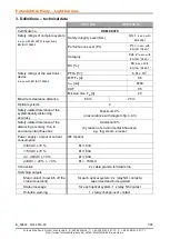
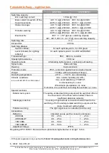
It is only allowed to control the crane movement by using the normally open contacts
NO
11
& NO
12
(system 1) and NO
21
& NO
22
(system 2)
The two separate normally open contacts NO
11
& NO
12
and NO
21
& NO
22
are provided to
make a connection with a safety control device which may need two contacts for the
safety function.
If the following control unit does not need separated contacts then the normally open
contacts NO
11
& NO
12
and NO
21
& NO
22
has to be connected per system in series.
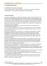
The follow-up circuit for the safety-related shutdown of the travel movement must take
into account the relevant product standard for the applicable crane type, e.g. EN 15011.
The external power supply has to fulfil the rules for low voltage with safe isolation (SELV,
PELV) in accordance with EN 60204-1.
A protective earth connection is essential for protection against electric shock from
exposed conductive parts.
It is not allowed to use the normally closed contacts NC
11
||NC
12
(system 1) and
NC
21
||NC
22
(system 2) also the change-over contacts NO
v
/COM
v
/NC
v
for safety purposes.
The contacts NC
11
||NC
12
, NC
21
||NC
22
and NO
v
/COM
v
/NC
v
can be used for signalling
purposes only just like a warning light or a warning flashlight.
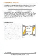
To prevent any contact bonding a fuse corresponding to the maximum switching capacity
of the utilization category has to be connected in line with each output contact (see
chapter 3).
For switching inductive loads just like relays or contactors a spark suppressor has to be
connected parallel to the inductive load.
AC:
Spark suppressor with RC-module
DC:
Spark suppressor with flyback diode
Notice: Spark suppressor modules must not connected parallel to the output switches!

