Fotoelektrik Pauly – Light barriers
E_52692 Ref. 2019-29
18/24
Fotoelektrik Pauly GmbH, Wahrbrink 6, D-59368 Werne, T: +49 2389/402 27-70, F: +49 2389/402 27-77
http://www.fotoelektrik-pauly.de, eMail: [email protected]
4.6 Information on assembly
The mounting has to be done in such a way that a misalignment caused by
mechanical vibration or bumps can be excluded. After finishing the fine alignment,
the transducer benches have to be tightened with the fixing screws.
The adjustment flange has to be locked with the mounting surface. Drill a hole of
6mm diameter and 20mm length close to each fastening hole and pin the
adjustment flange with the enclosed spring dowel sleeves.
The reflector must be installed in non-accessible areas or must be concealed.
The reflector should be protected from pollution by suitable measures e.g. a
protective housing.
The light beams of the systems must not be interrupted e.g. obstructions or
suspended objects. This must be taken into account at all events during assembly
and operation of the system.
It is to be absolutely ensured that the optics of the distancing assembly still has a
reflector view if both cranes have driven together to buffer separation distance!
When calculating the clearance distance the reaction time of the system must be
taken into consideration as decisive parameter for the stopping path of the crane.
The set clearance distance must be tested and recorded.
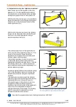
The reflector centre on the other crane must be situated at the optical device (lens) level
(see Fig. 4.5.1.6).
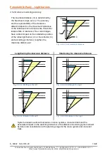
The devices on a crane and the adjacent crane must be mounted in such a way that their
optical system do not look into each other (directly or via reflections), Any mutual
influence must be excluded (see Fig.: 4.5.1-
2…-5).
In contrast to the assembly location of the reflector, assembly of the light barrier
(optoelectronics) must take place at the site where more pollution is to be expected.
The fixture of the CPV on the associated adjustment flange must be done by means of
the provided fasteners.
The fastening of the reflector must take place using rivets, adhesive or welded
connectors or using the screws supplied (safety screws with locking wedge),so that
dismantling can only take place by destroying the fastening element.
During and after the adjustment, it must be ensured that the plastic (safety) inserted part
of the lock nut engages on the thread and the springs are pretensioned.
Assembly may only be performed by a trained professional.
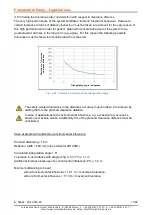
Triangulation angle
Δ ≥ 1° to be set, see graph Fig.: 4.5.3: Tolerance in relation to the
triangulation angle

