Fotoelektrik Pauly – Light barriers
E_52692 Ref. 2019-29
17/24
Fotoelektrik Pauly GmbH, Wahrbrink 6, D-59368 Werne, T: +49 2389/402 27-70, F: +49 2389/402 27-77
http://www.fotoelektrik-pauly.de, eMail: [email protected]
4.5.3 Taking the tolerances into consideration with respect to clearance distance
The very high performance of the system facilitates “tolerant” functional behaviour. However a
certain tolerance in terms of distance behaviour must be taken into account for the very reason of
this high performance in order for perfect, planned functional behaviour of the system to be
guaranteed at all times in the long term (e.g. aging). For this reason the following possible
tolerances must be taken into consideration from the start.
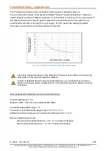
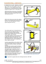
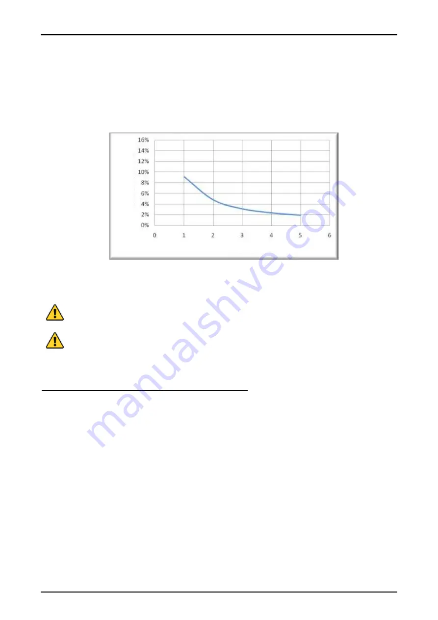
Fig.: 4.5.3: Tolerance in relation to the triangulation angle
The safety-related tolerances in the distances accuracy must be taken into account by
adding them to the planned clearance distance.
In case of applications with environmental influences, e.g. excessive fog, excessive
steam or excessive smoke, additionally 8% of the planned clearance distance must be
considered
Case example with and without environmental influences:
Planned distancing = 15 m
Reflector width = 400 mm (crane reflector 4R100BL)
Calculated triangulation angle 1.5°
Tolerance in accordance with diagram fig. 4.5.3: 7%
≙
1,1 m
Additional tolerance because of environmental influences: 8%
≙
1,2 m
Minimum distancing to be set
without environmental influences = 16.1 m + movement tolerance.
with environmental influences = 17,3 m + movement tolerance.
D
e
v
ia
ti
on
in
%
f
ro
m
t
he
c
le
a
ra
nce
d
is
ta
nce
Triangulation angle in degrees

