PAU Edge540 Instruction Manual Download Page 6


6


Chapter 3 

Landing Gear and Tail Wheel Assemblies 


Now that we’re ready for assembly, we are going to start with the main landing gear first.  You will need to 
locate the following parts to begin assembly. 


Place an “

×

×

×

×

” to ensure task completion: 


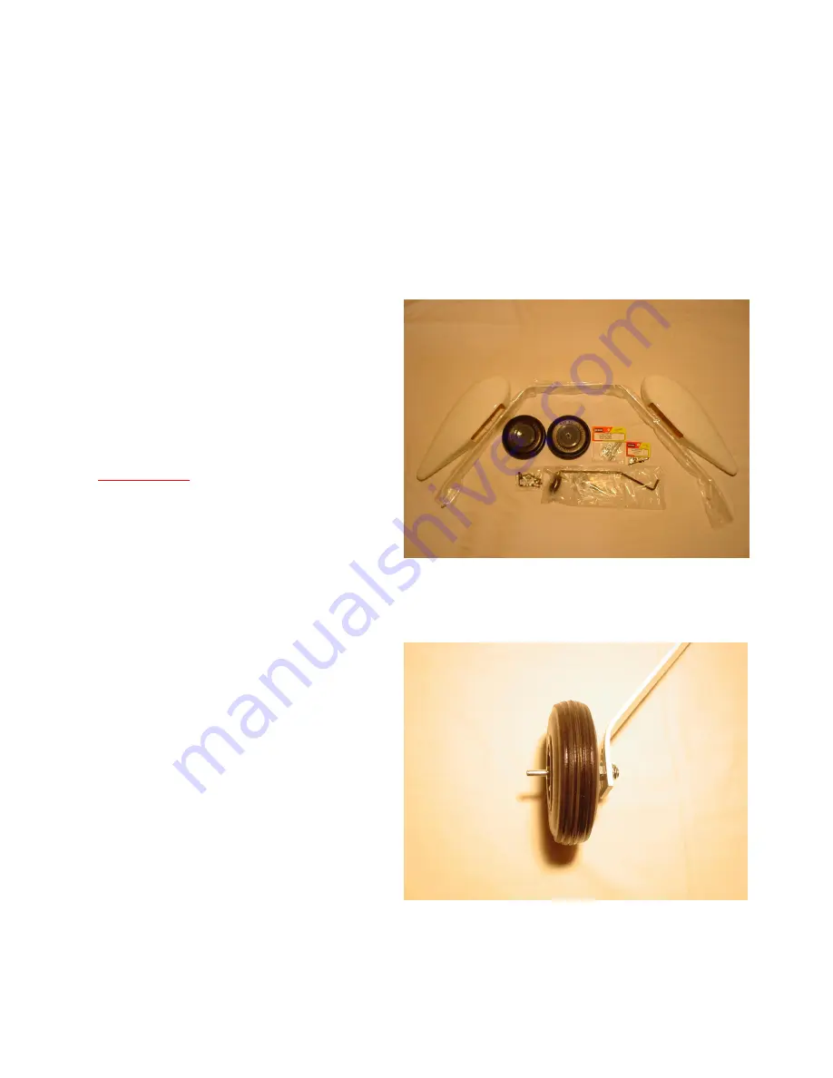
What you will need in this chapter for the main gear: 


Aluminum main gear 


One pair of 4.5” inch wheels 


One pair of wheel pants 


One pair of Dubro axles  


Four wheel collars 


Hardware pack marked “wheels” 


Fuselage 


Rudder 


Carbon Fiber Tail wheel assembly 

Not Provided:


½” and a 9/16” inch wrench  


Blue loc-tite  


Allen wrench for wheel collars  


White wood glue such as Elmer’s or 
Epoxy  


Fasten the axles to the main landing gear 
with the lock nuts.  


Using your four wheel collars and wheels, 
center you wheels on the axles.  Place the 
collars as close to the wheels as possible but 
ensure the wheels still rotate freely.  Again, 
we don’t want the wheel to move from side 
to side and contact the wheel pants.  Also, 
we recommend the use of loc-tite on the 
setscrews of the wheel collars to prevent 
them from vibrating loose.   


Summary of Contents for Edge540

Page 1: ...the podium for some time to come The PAU Edge is no different Designed with 2963 sq inches of wing area while keeping the total weight down has made this aircraft a true performer All wood constructio...

Page 2: ...nd propeller 8 channel computer radio and receiver recommended Batteries and switches with regulators if using Ion batteries Six aileron servos rated at least at 150oz of torque Four elevator servos r...

Page 3: ...embly 1 Canopy 1 Carbon fiber wing 1 Carbon fiber stabilizer tube 4 Nylon wing retention bolts 10 H9 titanium pushrods turnbuckles 1 set of Dubro wheel collars 1 pair of Dubro wheel axels 1 HD Dubro p...

Page 4: ...sure a scratch free finish Place an to ensure task completion Go over you model as necessary with a covering iron to insure all joints seams and corners are sealed properly Use your iron to ensure the...

Page 5: ...refully cut through the covering and into the laser cut lines in the fuse Remove the covering and carefully remove the wood within the frame Test fit the windows as some slight trim work may be requir...

Page 6: ...ack marked wheels Fuselage Rudder Carbon Fiber Tail wheel assembly Not Provided and a 9 16 inch wrench Blue loc tite Allen wrench for wheel collars White wood glue such as Elmer s or Epoxy Fasten the...

Page 7: ...ssion nuts Now lets get the tail wheel assembly installed Once the mains are on find the holes for the tail wheel assembly and open Once the mains are on find the pre marked holes for the tail wheel a...

Page 8: ...ng the end on the rubber grommets of the servo Mark the drilling location for the 4 40 bolts Drill the holes for the 4 40 bolts in the wheel pants at the locations you ve marked Apply some white wood...

Page 9: ...opy to the fuselage access hatch to determine screw locations Mark four to eight evenly spaced locations for the screws on each side Double check to ensure all the marked screw locations will go into...

Page 10: ...e you can use the pre marked firewall this may by slightly off due to variances when cutting the cowl from the molds DA 150 170 installation The firewall is pre marked so you ll just need to center yo...

Page 11: ...you will end up with a professional installation that will make an impression at the field Close the choke and place a piece of tape over the carburetor inlet and exhaust outlet to keep out any dust w...

Page 12: ...e holes of the trailing edge Apply epoxy to one side of the hinges and insert them into the holes figure 73 74 and 75 11 Apply epoxy into the leading edge holes of the control surface and the other si...

Page 13: ...ol surface fully deflected up and iron it in place Check to make sure you still have full surface travel once you have completed figure 78 79 and 80 Tip 5 Optional step After your epoxy has cured it w...

Page 14: ...elevators Two or three servos for rudder equaling 800oz One throttle servo 70oz or better Ten 1 5 aluminum servo arms One or two 3 arms to tie rudder servos One 4 offset rudder servo arm One Fuel dot...

Page 15: ...position Screw in your two HD ball links onto the counterclockwise ends of the 2 5 H9 push rods and screw the other end into the control horn Ensure everything is still centered Don t forget to add lo...

Page 16: ...l servo arms to tie the two or three servos together as well as a servo matching devise Install your pull pull cable using the 60lbs leader provided Please discard the wire provided with the Dubro pul...

Page 17: ...ach side of the fuse They will both accept HD standard switches Mount your switches at this time Install the fuel filling device in a location of your choice In this case we installed it just behind t...

Page 18: ...the wings installed mark the anti rotation pins inch from the fuselage side Remove the wings and drill a small hole in the anti rotation pins You can find appropriate sized hitch pins at most local ha...

Page 19: ...70 expo 45 degrees for elevators with 40 to 70 expo 45 degrees for rudder with 30 to 70 expo or as much as you can stand for hardcore flyers CG Range is 7 1 2 to 9 inches or center of tube Place an to...

Page 20: ...ardware Gently tug on each surface to make sure the hinges are properly bonded Check the four 4 40 horizontal stabilizer fasteners and ensure they re in place and secured Check all servos for mounting...

Page 21: ...r throttle management and avoid high speed when executing high stress maneuvers such as Walls Parachutes and Blenders As a general rule the throttle must be at idle position whenever the nose is point...

Page 22: ...22 Throw Template If printing from Adobe turn off page scaling Cut out around all the dotted lines...

Reviews: