Bridged PPP configuration
56
Model 6081RC Network Access Server Getting Started Guide
6 • PPP configuration
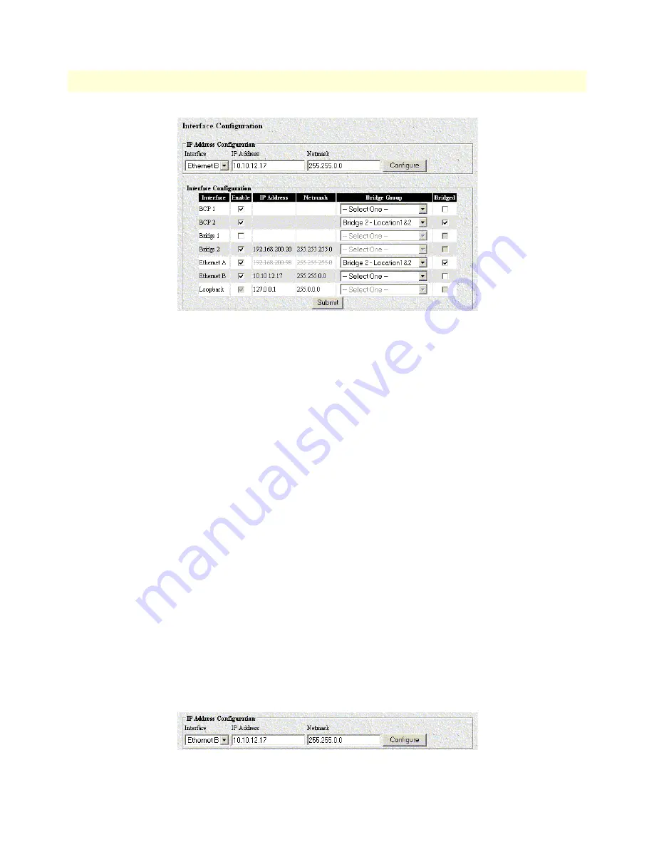
Figure 34. Interface Configuration page
To activate a PPP/BCP connection between the remote CPEs (Location1&2) and the 6081RC bridge, do the
following:
1. Click the check boxes in the Enable column to add a check to the BCP 1, BCP 2, and Bridge 2) entries in
the Interface column (see
figure 34
).
Note
Although we are not using BCP 1 to bridge data, the 6081RC needs
to see this default PPP module enabled in order to activate the rest of
the sessions.
2. In the BCP 2 row (see
figure 34
), use the drop down menu under the Bridge Group column to select the
Bridge 2 - Location1&2” option. Under the Bridged column, place a checkmark on the box corresponding
to BCP2.
3. Click on the
Submit
button to save changes.
At this time, a PPP/BCP connection between the 6081RC and the remote CPEs may have been established
(check this by clicking on the PPP main menu option), each PPP connection will be displayed in color code,
the color green meaning that a connection has been established. However, there is not yet a connection
between the PPP/BCP modules and the Ethernet port (that is, the bridge module does not have a path to the
Ethernet port and therefore no bridged data can be sent to the a LAN).
To activate a connection between the bridge module and the front panel Ethernet interface (Ethernet A), do the
following:
1. In the Ethernet A row (see
figure 34
), click to add a checkmark on the box under the Enabled column.
2. In the IP Address Configuration section of the Interface Configuration page (see
figure 35
), select Bridge 1
from the Interface menu.
Figure 35. IP Address Configuration section of the Interface Configuration page


