background image

3.2  DETAILED SWITCH SETTINGS

This section provides detailed information about the function of

each DIP switch and lists all possible settings.

Switch 1:  Hardware/Software Control

The setting for Switch 1 determines whether these interface

converters will control either hardware or software flow control.

Switch 2:  Enable/Disable LED Indicator

The setting for Switch 2 determines whether the LED indicator is

enabled or disabled.

5

Flow Control SW1

Hardware

OFF

Software

ON

LED

SW2

Enabled

ON

Disabled

OFF

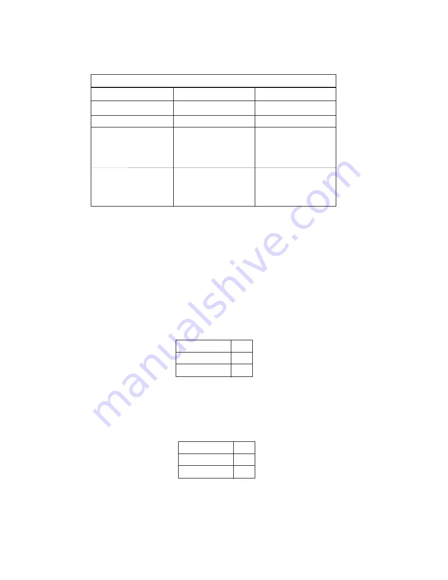
DIP SWITCH SUMMARY TABLE

Position

Function

Factory Default

SW1

Flow Control

Off

SW2

LED Indicator

On

SW3

Data, Parity, Stop Bits

Off

SW4

Data, Parity, Stop Bits

Off

SW5

Data, Parity, Stop Bits

Off

SW6

Data Rate

Off

SW7

Data Rate

Off

SW8

Data Rate

Off

Hardware

Enabled

8B, NP, 1S

38400 bps

}

}

5.0  OPERATION

Once your interface converter is properly configured and installed,

it should operate transparently—as if it were a standard cable
connection.  Operating power is derived from the RS-232 data and
control signals; there is no “ON/OFF” switch.  

5.1  LED  STATUS MONITORS

The Model 2036 and 2037 feature an easy-to-read LED that shows

the operating status of the Model 2036.  Figure 1 (page 4) shows the
location of these LEDs.  The following chart describes the LED’s status
codes.

Please refer to the following key to  interpret the above status

codes:

8

LED Codes

●  ●  

●  

———

●  ●  

●  

———

Computer is sending data

● 

———

●  

———

●  

———

Serial device is connected; computer is 

not sending data

●  ●  

———

●  ●  

———

Both serial and parallel devices are

connected; computer not sending data

●  

●  

———

●  

●  

———

Printer not ready, data held in buffer

●  ●  ●  ●  

———

●  ●  ●  ●

Computer ignoring flow control, data lost

Key:

Blink

Short pause

———

Long pause

Summary of Contents for 2036

Page 1: ...E 301 975 1000 TECHNICAL SUPPORT 301 975 1007 http www patton com Part 07M2036 C Doc 102061U Rev D Revised 1 22 08 MODEL 2036 and 2037 Parallel to Serial Serial to Parallel Interface Converters An ISO...

Page 2: ...and if not installed and used properly that is in strict accordance with the manufacturer s instructions may cause interference to radio and television reception They have been tested and found to co...

Page 3: ......

Page 4: ...el to Serial Converter automatically convert RS 232 serial data to parallel data format or vice versa Incorporating advanced microprocessor technology the Model 2036 and 2037 automatically sense and s...

Page 5: ......

Page 6: ...ow control Switch 2 Enable Disable LED Indicator The setting for Switch 2 determines whether the LED indicator is enabled or disabled 5 Flow Control SW1 Hardware OFF Software ON LED SW2 Enabled ON Dis...

Page 7: ......

Page 8: ...ches just plug your converter in to a standard cable and you re ready to go Figure 3 illustrates the proper connections for the Model 2036 and 2037 If you have special ordered a non standard connector...

Page 9: ......

Page 10: ...600 19200 38400 57600 and 115200 bps LED LED displays status and operating condition Power Supply Uses power from RS 232 interface 9Vdc maximum typical current 20mA Typical maximum power consumption 1...

Page 11: ......

Page 12: ...ECTIONS 11 Converter Serial Port Serial Data Serial Software Serial Hardware Function Connected Flow Ctrl Signal Flow Ctrl Signal XON XOFF DTR CTS DSR Serial to Parallel DTE TD RD CTS DSR Serial to Pa...

Page 13: ......

Page 14: ...DTR CTS RD TD GND 6 4 8 20 5 3 2 7 DATA BIT 1 DATA BIT 2 DATA BIT 3 DATA BIT 4 DATA BIT 5 DATA BIT 6 DATA BIT 7 DATA BIT 8 2 3 4 5 6 7 8 9 1 10 11 12 13 15 STROBE ACKNOWLEDGE BUSY PAPER END SELECT ER...

Page 15: ......

Page 16: ......

Reviews: