


3.0 CONFIGURATION
The Model 1226 is simple to install, and is designed for excellent
reliability: just set it and forget it. The following instructions will help
you set up and install the Model 1226 properly. If you have any
questions, please call Patton Technical Support at (301) 975-1007.
3.1 CONNECTING TWO MODEL 1226s
(Parallel to Parallel)
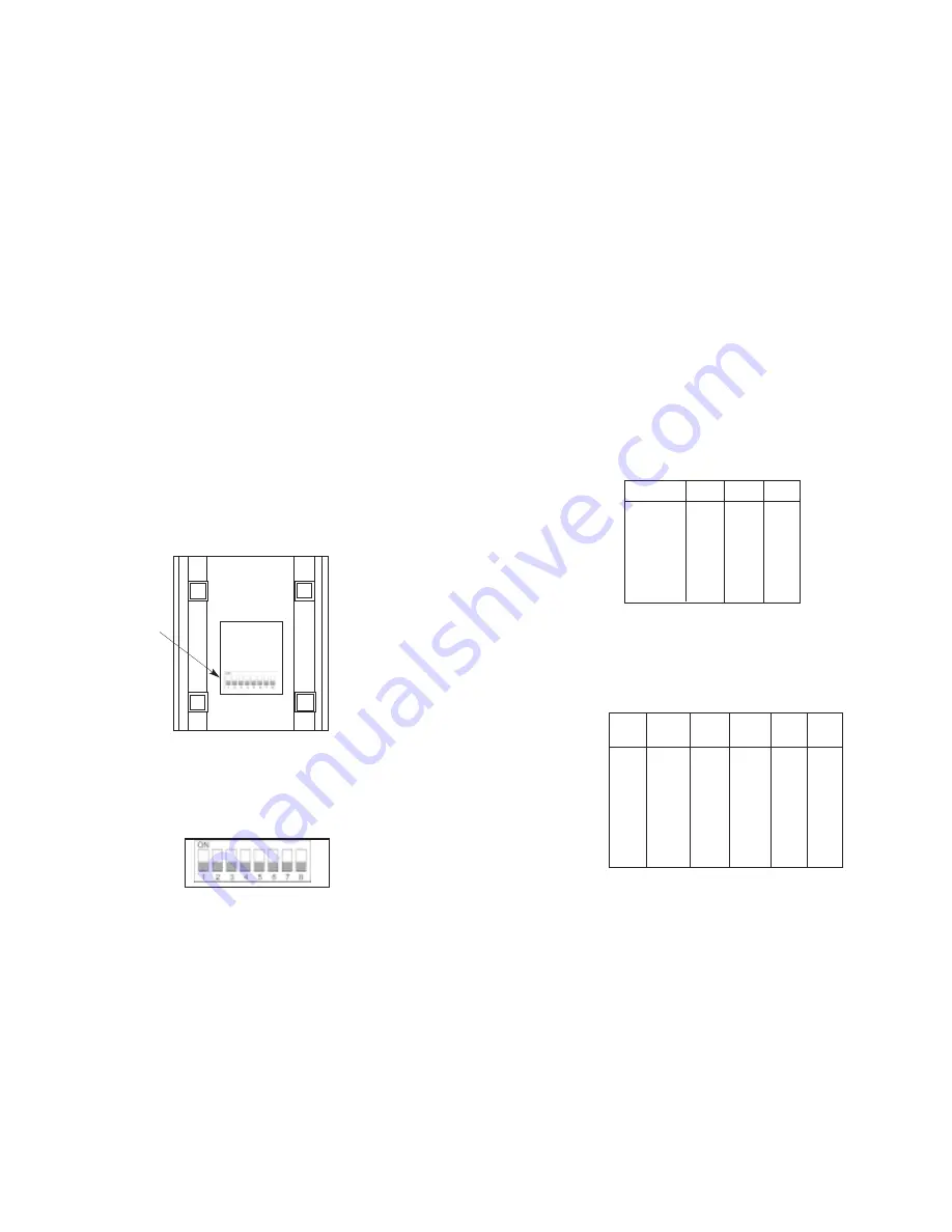
The Model 1226 uses a set of eight DIP switches (see Figure 1)
that allow configuration to a wide range of applications. Because all
eight switches are in one externally accessible DIP switch package,
there is no need to open the Model 1226's case for configuration. The
configuration switches allow you to select data rates, parity, word length
and flow control selection. The following section describes all switch
locations, positions and functions.
The Model 1226 uses a DIP switch package (see Figure 2). To
configure your unit, use a small screwdriver and gently push each
switch to its proper setting. The ON and OFF positions are shown in
Figures 1 and 2.
3
3.1.1 DETAILED SWITCH SETTINGS
This section provides detailed information about the function of
each DIP switch and lists all possible settings.
Switches 1 through 3: Frequency and Data Rate
Switches 1 through 3 determine the data rate for the Model 1226.
Use the following chart to configure your equipment:
NOTE: Factory defaults are in
bold italics.
Switch 4 through 6: Data, Parity and Stop Bit
Switches 4 through 6 are used to specify the data, parity and stop
bits. The following table shows the settings that may be used:
NOTE: Factory defaults are in
bold italics.
4
Figure 1. Underside of the Model 1226, showing location of DIP switches
Figure 2. Close-up of the Model 1226 configuration switch package
1200
ON
OFF
OFF
2400
ON
OFF
ON
4800
OFF
ON
ON
9600
ON
ON
OFF
19200
ON
ON
ON
38400
OFF
OFF
OFF
57600
OFF
OFF
ON
Data Rate
SW1
SW2
SW3
FRONT
REAR
DIP Switches
7B
EP
1S
ON
ON
ON
7B
OP
1S
ON
ON
OFF
7B
NP
2S
ON
OFF
ON
7B
EP
2S
ON
OFF
OFF
7B
OP
2S
OFF
ON
ON
8B
EP
1S
OFF
ON
OFF
8B
OP
1S
OFF
OFF
ON
8B
NP
1S
OFF
OFF
OFF
Stop
Data
Parity
Bit
SW4
SW5
SW6


