background image

Switch 7:  Reserved for Future Use

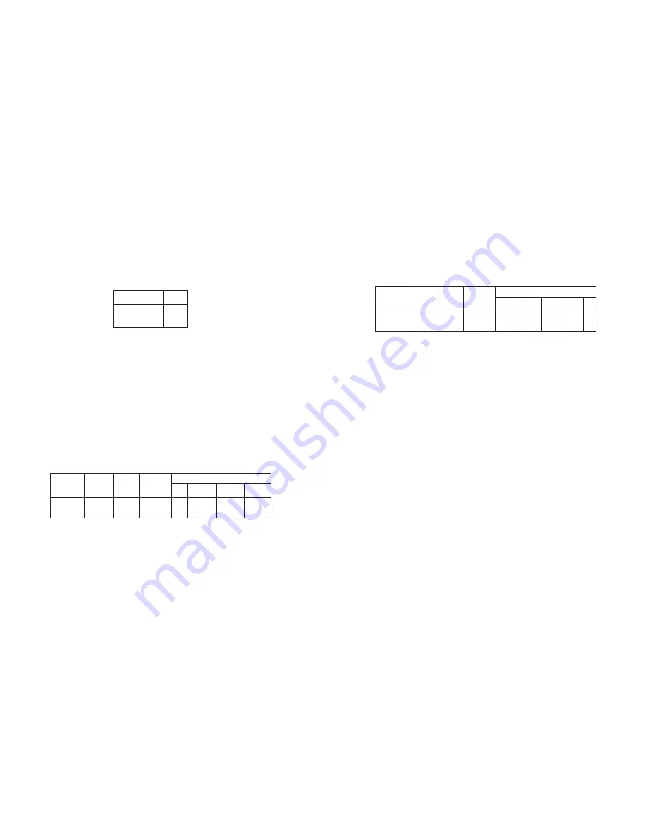
Switch 8:  Hardware/Software Control

The setting for Switch 8 determines whether the Model 1226 uses

either hardware or software flow control.

NOTE: Factory defaults are in 

bold italics.

3.2  CONNECTING A MODEL 1226 TO A MODEL 1060

(Parallel to Serial/ Serial to Parallel)

When connecting a Model 1226 to a Model 1060, you need to

configure both units.  First, set the DIP switches on the Model 1226 as
indicated in Section 3.1.1.  Then configure the Model 1060 by following
the instructions below.

3.2.1  USING THE MODEL 1060 AS A TRANSMITTER

If you are using your Model 1060 as a transmitter, you must

configure the Model 1060 according to the chart below.  Do not change
the settings on your Model 1226.

Next, you will need to configure your computer’s settings.  If you

are using DOS, type the following command at the C prompt:

MODE COM2:  9600,n,8,1,p

If you are not using DOS, call Patton Technical Support at

(301) 975-1007 for further assistance.

5

3.2.2  USING THE MODEL 1060 AS A RECEIVER

If you are using your Model 1060 as a receiver, you must configure

the Model 1060 according to the chart below.  Do not change the
settings on your Model 1226.

6

Control

Control

Carrier

Switch Settings

Mode

Input

Output Controlled

(DCE/DTE)

(C

In

)

(C

Out

)

by (C

In

)

1

2

3

4

5

6

7

DCE

4, 11, 20

8

Enabled

OFF ON

ON

ON OFF OFF ON

DCE

4, 11, 20

6

Enabled

OFF OFF OFF ON ON

ON ON

Control

Control

Carrier

Switch Settings

Mode

Input

Output Controlled

(DCE/DTE)

(C

In

)

(C

Out

)

by (C

In

)

1

2

3

4

5

6

7

DTE

5, 6, 8

4

Enabled

OFF ON

ON

ON OFF OFF ON

DTE

5, 6, 8

11, 20

Enabled

OFF OFF OFF ON ON

ON ON

Hardware

OFF

Software

ON

Flow Control SW8

Summary of Contents for 1226

Page 1: ...USER MANUAL MODEL 1226 Parallel Short Range Modem SALES OFFICE 301 975 1000 TECHNICAL SUPPORT 301 975 1007 http www patton com Part 07M1226 B Doc 104031UB Revised 08 13 99...

Page 2: ...ber may be obtained from Patton Electronics Technical Service at 301 975 1007 Packages received without an RMA number will not be accepted Patton Electronics technical staff is also available to answe...

Page 3: ...proper setting The ON and OFF positions are shown in Figures 1 and 2 3 3 1 1 DETAILED SWITCH SETTINGS This section provides detailed information about the function of each DIP switch and lists all po...

Page 4: ...on your Model 1226 Next you will need to configure your computer s settings If you are using DOS type the following command at the C prompt MODE COM2 9600 n 8 1 p If you are not using DOS call Patton...

Page 5: ...CV 5 XMT 6 GND 6 RCV 7 GND 8 NC When connecting two Model 1226s it is necessary to use a cross over cable The diagram below shows how a crossover cable should be constructed for an environment where b...

Page 6: ...hat indicate the condition of the modem and communication link Figure 5 shows the front panel location of each LED Following Figure 5 is a description of each LED s function The Power LED glows solid...

Page 7: ...NDIX A SPECIFICATIONS Parallel Interface DB 25 female Data Rate Up to 57 6 Kbps Range Up to 14 miles Transmission Full duplex over 4 wire shielded or unshielded twisted pair Line Interface RJ 11 RJ 45...

Page 8: ...uter 6 Data Bit 5 Computer 5 Data Bit 4 Computer 4 Data Bit 3 Computer 3 Data Bit 2 Computer 2 Data Bit 1 LSB Computer 1 Data Strobe Active LOW Computer SOURCE TRANSMITTER RECEIVER DB 25 SOURCE Common...

Reviews: