


C.
Connect one pair of wires to RCV+ and RCT- (receive positive and
receive negative) on the terminal block, making careful note of
which color is positive and which color is negative.
D.
If there is a shield around the telephone cable, it may be connected
to “G” on the terminal block. To avoid ground loops, we
recommend connecting the shield at the computer end only. A
ground wire is not necessary for proper operation of these units.
E.
When you have finished connecting the telephone line to units at
both ends, it should look similar to the following diagram:
5.0 OPERATION
Once both Model 1226s have been connected to each other and to
their corresponding parallel input and output devices, you are ready to
operate the units. The units should function transparently, just like a
cable. There is no ON / OFF switch.
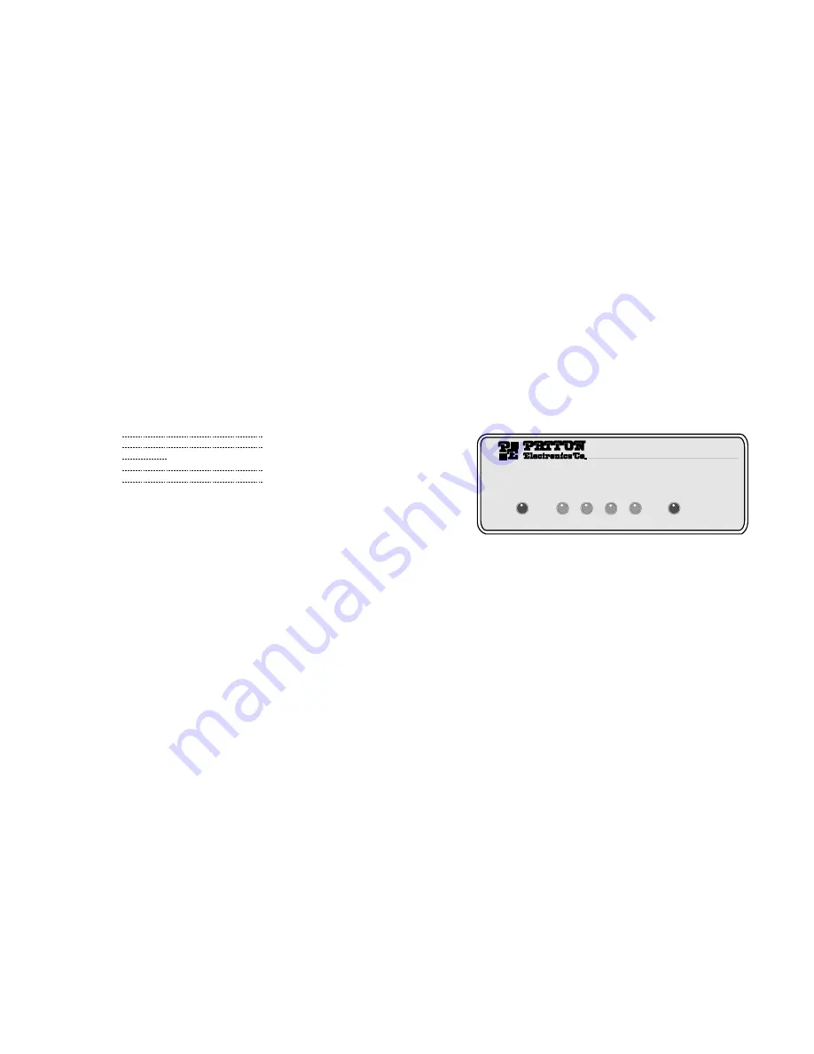
5.1 LED STATUS MONITORS
The Model 1226 features six front panel status LEDs that indicate
the condition of the modem and communication link. Figure 5 shows
the front panel location of each LED. Following Figure 5 is a
description of each LED's function.
●
The “Power” LED glows solid green when power is applied to the
Model 1226.
●
The “TD” indicator blinks red and green with data activity. Red
indicates that the Model 1226 is not currently transmitting data.
●
The “RD” indicator blinks red and green with data activity. Red
indicates that the Model 1226 is not currently receiving data.
●
The “Control In” indicator usually glows green. However, it glows
solid red when flow control comes from the remote Model 1226.
●
The “Control Out” indicator usually glows green. However, it glows
solid red when flow control comes from the local Model 1226.
●
The “Status” indicator shows data activity by blinking green in a
variety of codes. The chart on the following page describes these
codes:
9
10
Model 1226 Parallel Short Range Modem
Power
TD
RD
Control
IN
Control
OUT
Status
Figure 5. The Model 1226’s front panel LEDs
XMT +
RCV+
XMT -
RCV -
G
G
RCV -
XMT -
RCV +
XMT +
To Shield (Optional)
}
One Pair
}
One Pair


