Page 3 of 9
ASSEMBLY INSTRUCTIONS(contiuned)
FUNCTION AND OPERATION
A
3
A
BB
CC
4
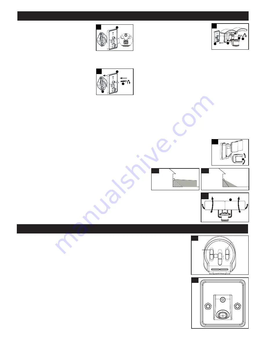
3. Pull out the source wires from the outlet
box.Connect the black wire from the
outlet box to the “L” interface of the
terminal station on the mounting
bracket(A). Connect the white wire from
the outlet box to the “N” interface of the
terminal station on the mounting bracket(A).
Carefully tuck the wires back into the outlet box.
N
L
4. Place mounting bracket(A) against the
outlet box, insert the mounting bracket
screw(BB) through the mounting
bracket hole, thread mounting bracket
screw(BB) into the center hole of the
mounting strap(CC). Tighten the
mounting bracket screw(BB) securely.
Ÿ:KHQPRXQWLQJWRDZDOOWKH³83´DUURZPXVWSRLQW
upward.
Ÿ:KHQPRXQWLQJWRDQHDYHWKH³83´DUURZPXVWSRLQW
toward the building.
DD
B
DD
A
EE DD
5
5. Attach the back plate(B) of the light
fixture to the mounting bracket(A),
secure it with the fixture mounting
screw(EE). Then push the decorative
cover(DD) firmly into the fixture
mounting screw(EE) hole on the light
fixture.
Adjusting the Sensor Head:
1. a: Aim sensor head toward desired detection area, maintaining a 5° - 40° downward angle to allow
moisture to drain. (See Fig.1)
Note: Make sure sensor head is positioned with control knob facing towards the ground.
DD
D
Adjustment Sensor Lower For Short Coverage
Adjustment Sensor Higher For Long Coverage
Fig.2-1
Fig.2-2
Fig.1
b: You can rotate the sensor head up and down to change the coverage area . Walk through the
detection zone at the farthest distance you wish to detect motion.
2. Range set too high may increase false triggering. (See Fig.2-1,2-2)
1. You can adjust the sensitivity of the motion sensor by using the “SENSITIVITY” selector
located on the right side of the bottom surface of the sensor. (See Fig.4)
2. Adjust motion sensor sensitivity to HIGH (H), MEDIUM (M), or LOW (L) to achieve desired
performance.
3. Approximate range for each setting: 25 ft. (L), 45 ft. (M), 70 ft. (H).
Fig.3
1. Gently grasp the light heads(C) and tilt them up or down, left or right to adjust the light coverage
DUHD.HHSWKHOLJKWKHDGVDWOHDVWÝPPDZD\IURPWKHVHQVRU6HH)LJ
2.
.HHSWKHOLJKWKHDGVÛEHORZKRUL]RQWDOWRDYRLGZDWHUGDPDJHDQGHOHFWULFDOVKRFN
Adjusting the Light Head:
Sensitivity of Motion Sensor:
DD
C
Fig. 4
Mode
Mode
TEST
AUTO
RESET
3MIN
1MIN
5S
5MIN
L
M
H
CUSTOM
SETTINGS
SENSITIVITY
Sensitivity
Choose a mode by sliding the switch on the bottom of the sensor. (See Fig.4)
Note: When power is first applied, the light will turn on to 100% brightness. The sensor
will take 30 seconds to warm up.
1. Test mode (daytime or nighttime operation )
Ɣ6OLGHWKHVZLWFKRQWKHOHIWVLGHRIWKHVHQVRUWRWKH³7(67´SRVLWLRQ6HH)LJ
Ɣ:LWKWKHSRZHURQWKHOLJKWWXUQ
s to low-level brightness automatically.
Ɣ7KHOLJKWWXUQVWRKLJKOHYHOEULJKWQHVVZKHQPRWLRQLVGHWHFWHGDQGVWD\VRQDVORQJDV
the motion continues. Then it reverts back to low-level brightness about 5 seconds after
motion is no longer detected.
Note: You can adjust the low-level (0~50%) and high-level (50~100%) brightness by
using the brightness switch on the back plate. (See Fig. 5)
6. With silicone caulking compound, caulk completely around
where the mounting bracket meets the wall surface.
CAUTION: Be sure to caulk completely where the
mounting bracket meets the wall surface to prevent
water from seeping into the outlet box.
Fig. 5
HIGH LEVEL
75%
25%
100%
50%
50%
0
LOW LEVEL


