b)
Tungsten-arc inert-gas welding (TIG);
c)
Semi-automatic welding in safety gas environment
(MIG/MAG);
5
–
Selected welding mode indicator;
6
–
Wire-filling button (no gas supplied);
7
–
Buttons for adjusting parameters to decrease and increase (default: wire feed
speed);
8
–
Digital display of the wire feeder;
9
–
Safety gas check button (no wire feed);
10
–
Button for selecting functions of the wire feeder;
11
–
Lifting protective cover for wire feeder and coil compartment;
12
–
KZ-2 EURO type connector for semi-automatic torch
connection;
13
–
Power supply plug to the wire feeder;
14
–
Source on/off button (decorative color and shape);
15
–
Fuse holder (4A) for wire feeder;
16
–
Shielding gas connection;
A
–
Power socket "+" of bayonet type:
a)
For MMA welding, the electrode cable is connected (in rarer cases, when special electrodes are used, the "ground" cable is
connected);
b)
For TIG welding, only the "ground" cable is connected;
c)
In the case of semi-automatic MIG/MAG welding with
solid
wire, the cable to the feeder shall be connected;
d)
In the case of semi-automatic MIG/MAG welding with
flux
wire, "ground" cable connected;
a)
For MMA welding, ground cable is connected (in rarer cases, when special electrodes are used, the electrode cable is connected);
b)
For TIG welding, only the argon torch is connected;
c)
In the case of semi-automatic MIG/MAG welding with
solid
wire, the "ground" cable is connected;
d)
In the case of semi-automatic MIG/MAG welding with
flux
wire, the cable to the feeder shall be connected.
START-UP
The welding unit is designed exclusively for MMA welding, tungsten-arc inert-gas (TIG) welding, as well as metal-arc inert-gas welding/metal
active gas welding (MIG/MAG). Other use of the machine is considered undue. The manufacturer is not responsible for damage cause by
undue use of the machine. Intended use of the machine implies adherence to instructions of this operating manual.
INSTALLATION REQUIREMENTS
The machine must be placed so as to ensure free inlet and outlet of cooling air through vent holes on the front and the rear panels. Take care
that metal dust (for example, during emery grinding) does drawn directly into the machine by the cooling fan.
POWER CONNECTION
The standard welding unit is rated for mains voltage is 220V (-27% +18%).
Caution!
When the unit is connected to a mains voltage higher than 270V all manufacturer's warranty obligations become invalid! The
manufacturer's warranty obligations also become invalid in case of an erroneous connection of the mains phase to the source ground.
The mains connector, the cross-sections of the mains cables, as well as the mains fuses need to be selected based on the unit technical data.
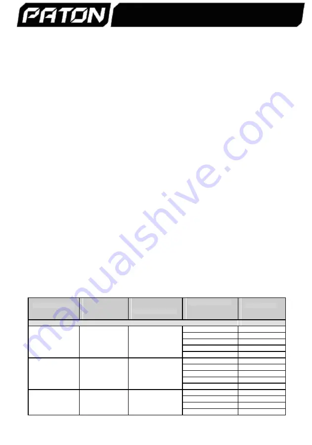
Electrode to be used
Set current value
Wire cross-section
Cross-section of each
Maximum cable
core of the mains
in MMA mode
for MMA and TIG
diameter at MIG/MAG
length, m
cable, mm²
1 x 220V/230V
–
StandardMIG-160, StandardMIG-200, StandardMIG-250
1.0
75
1.5
115
Ø
2 mm
Max. 80А
Max.
Ø
0.6 mm
2.0
155
2.5
195
4.0
310
1.5
75
2.0
105
Ø
3 mm
Max. 120А
Max.
Ø
0.8 mm
2.5
130
4.0
205
6.0
310
2.0
80
Ø
4 mm
Max. 160А
Up to
Ø
1.0 mm
2.5
100
4.0
165
6.0
245
-3 -
PATON
EuroMIG
DC MMA/TIG/MIG/MAG
Summary of Contents for EuroMIG
Page 1: ......


