


PS-3220
Mounting the Wireless Rotary Motion Sensor
5
013-15949A
Collecting Data
•
Select the Start button to begin collecting data.
PASCO Capstone
Connecting the Sensor to a Tablet or a Computer via Bluetooth
•
For PASCO Capstone, select
Hardware Setup
in the Tools palette. In
Hardware Setup
the sensors are
ordered by proximity to the device. Select the address that matches the Device ID XXX-XXX number on the
sensor.
Select a display in the main window or from the
Display
palette. In the display, use the
<Select Measurement>
menu to pick a measurement to be shown.
Connecting the Sensor to a Computer with the Micro USB Cable
•
Connect the micro end of the included Micro USB Cable into the micro USB port on the end of the sensor.
Connect the other end of the Micro USB Cable to a USB port on the computer, or into a powered USB hub
connected to the computer.
•
In PASCO Capstone, select a display in the main window or from the
Displays
palette. In the display, use the
<Select Measurement>
menus to pick the measurement to be shown.
Collecting Data
•
Select
Record
to begin recording data.
Troubleshooting the Sensor
•
If the sensor loses Bluetooth connection and will not reconnect, try cycling the ON button. Press and briefly
hold
the button until the status LEDs blink in sequence, and then release the button. Start the sensor in the
usual way.
•
If the sensor stops communicating with the computer software or tablet application, try restarting the software
or application. If the problem remains, press and
hold
the ON button for 10 seconds and then release. Start the
sensor in the usual way.
•
Turn Bluetooth off and then back on. Retry.
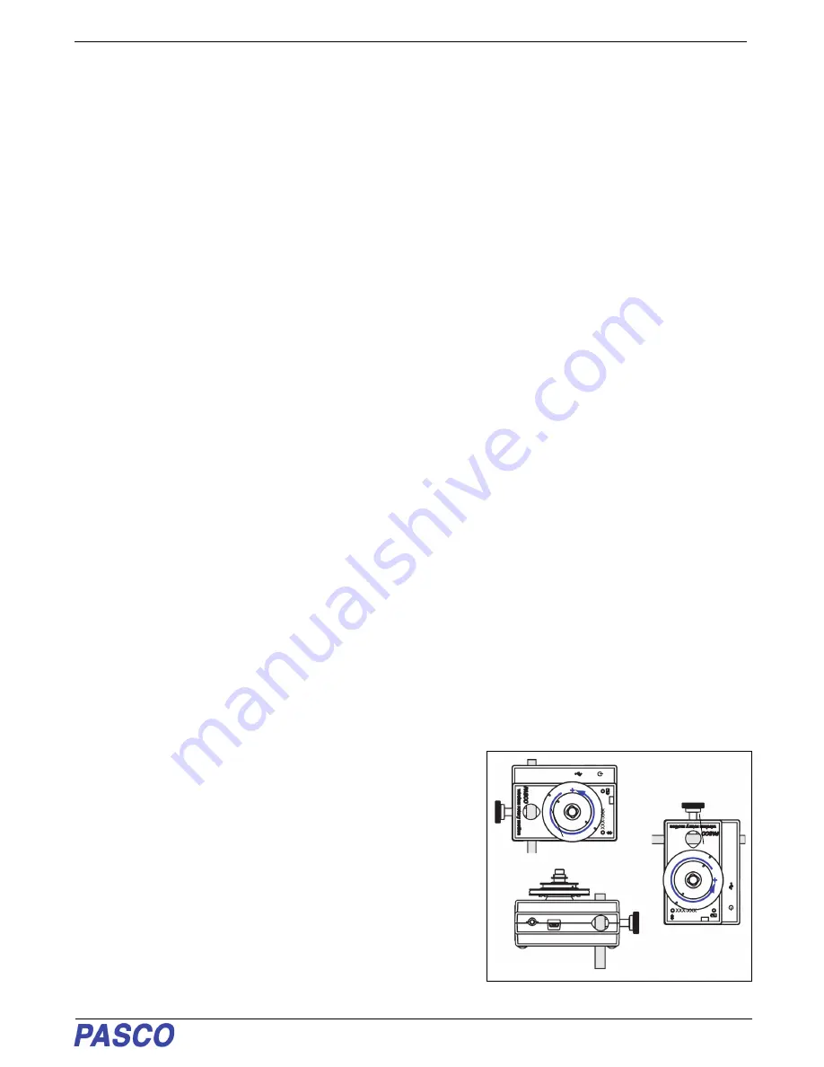
Mounting the Wireless Rotary Motion Sensor
The sensor case has two support rod holes that fit rods up to 12.7 mm
in diameter, such as the ME-8736 45 cm Stainless Steel Rod, and the
case can be put on the support rod using either of the support rod
holes.
It is possible to mount the Wireless Rotary Motion Sensor horizontally
on a support rod with the Three-step Pulley facing up or facing
sideways. You can mount the sensor vertically with the pulley facing
forward.
When mounted on a track as shown, a Rotary Motion Sensor could be
used to measure the motion of a PASCO Cart as it is pulled by a string
suspended over the Three-step Pulley of the sensor and attached to a
hanging mass.
Case


