background image

PS-3220

 Mounting the Wireless Rotary Motion Sensor

7

013-15949A

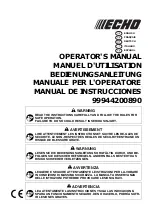
Attaching the Pendulum Accessory Rod (part of ME-8969 Pendulum Accessory) to the Wireless Rotary 
Motion Sensor

To mount the rod of the Pendulum Accessory to the Wireless Rotary 
Motion Sensor, orient the 3-step Pulley so that the large diameter step is 
away from the sensor case. The large diameter step has two pair of rod 
guides opposite each other on the top edge. Align the rod with the rod 
guides and use the captive screw in the center of the rod to attach the rod 
and pulley onto the sensor’s shaft.

Point Mass Setup

 Attach the center of the rod to the 3-step Pulley and 

shaft and mount the cylindrical masses at the ends of the rod to 
investigate the rotational inertia (moment of inertia) of point masses.

Pendulum Setup

 Attach the end of the rod to the 3-step Pulley and 

shaft. Mount a cylindrical mass on the rod to use the rod as a pendulum. Investigate 
the period of oscillation of the pendulum when the amount of mass or the position of 
the mass is changed. Investigate the period of oscillation as the amplitude of the 
swing is changed.

.

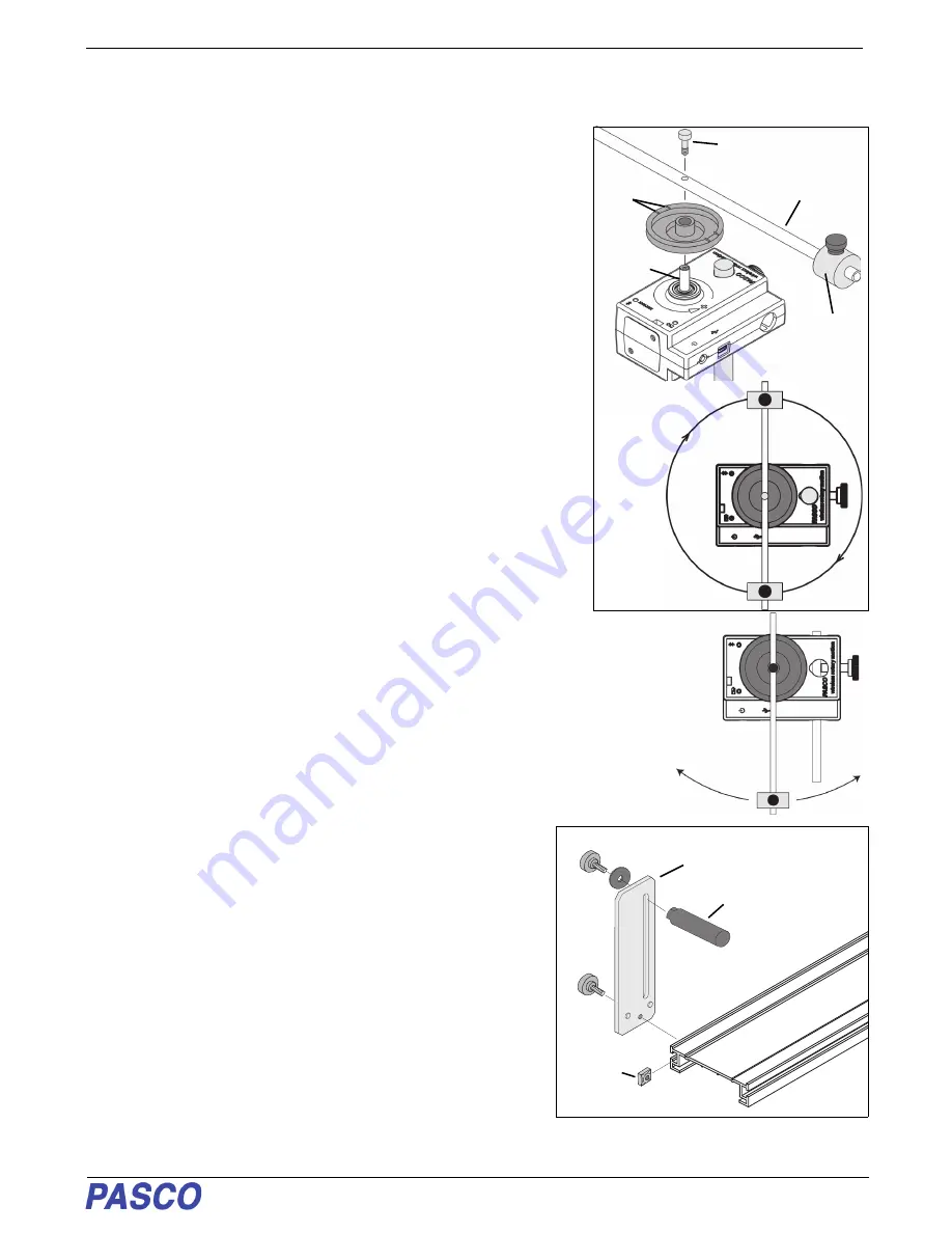
Mounting the Wireless Rotary Motion Sensor on a PASCO Track

The sensor can also be mounted on the short rod that is part of the 
Dynamics Track Mount Accessory (CI-6692).

Slide the square nut of the Dynamics Track Mount Accessory into the 
T-slot on the side of the track. Adjust the position of the mounting 
rod.on the Dynamics Track Mount Accessory.

When mounted on the track as shown, the Wireless Rotary Motion 
Sensor could be used to measure the motion of a PASCO Cart as it 
is pulled by a string suspended over the Three-step Pulley of sensor 
and attached to a mass hanger.

Pendulum 

Accessory Rod

Rod 

guides

Cylindrical 

mass

Shaft

Screw

Point Mass Setup

Dynamics 

Track Mount 

Accessory

Square 

nut into 

T-slot

Mounting rod

Summary of Contents for PS-3220

Page 1: ...w Check under Resources Equipment Included Equipment Included Wireless Rotary Motion Sensor Three step Pulley O ring Small Thumbscrew Micro USB Cable 1 meter Thumbscrew Required Item Part Number PASCO...

Page 2: ...he sensor has a platform for mounting a Super Pulley with Table Clamp optional Using the Sensor The sensor is designed to work with PASCO data collection software to measure position velocity and acce...

Page 3: ...hen the unit is fully charged The battery status LED will shine yellow as the battery is charging and will shine green when the battery is charged The battery is partially charged at the factory Initi...

Page 4: ...oth For SPARKvue select the Bluetooth icon In the Wireless Devices list The sensors are ordered by proximity to the device Select the correct address that matches the Device ID XXX XXX number found on...

Page 5: ...begin recording data Troubleshooting the Sensor If the sensor loses Bluetooth connection and will not reconnect try cycling the ON button Press and briefly hold the button until the status LEDs blink...

Page 6: ...side of the sensor To provide a known torque wrap a string around one of the steps of the 3 step Pulley Arrange the end of the string over the Super Pulley and attach a hanging mass Adjust the Super P...

Page 7: ...to the 3 step Pulley and shaft Mount a cylindrical mass on the rod to use the rod as a pendulum Investigate the period of oscillation of the pendulum when the amount of mass or the position of the mas...

Page 8: ...onto the shaft of the Wireless Rotary Motion Sensor Replace the gyroscope assembly on the vertical shaft See the PASCO web site at www pasco com for more information Experiments Experiments for the W...

Page 9: ...0 Experiments 9 013 15949A Rotational Resolution 0 00157 radian Maximum Rotation Rate 30 rotations per second Optical Encoder Bidirectional indicates direction of motion 4 000 divisions rotation Item...

Page 10: ...at vary by country and region It is your responsibility to recycle your electronic equipment per your local environmental laws and regulations to ensure that it will be recycled in a manner that prote...

Page 11: ...the More Info button Click the System Report button Select Bluetooth from the sidebar on the left underneath Hardware Scan down the list of information until you find LMP Version If your Mac is equip...

Page 12: ...Wireless Rotary Motion Sensor Appendix A Compatibility 12 013 15949A...

Page 13: ...and the resulting angular acceleration is measured Since I where is the angular acceleration which is equal to a r a linear acceleration and is the torque caused by the weight hanging from the thread...

Page 14: ...iddle of the groove on the clamp on Super Pulley 7 Adjust the Super Pulley height so that the thread is level with the 3 step pulley Procedure Part 1 Measurements for the Theoretical Rotational Inerti...

Page 15: ...unwinds from the 3 step Pulley 5 In the Graph display select the region of the data that represents when the Point Masses and Apparatus were accelerating 6 In the display select Linear from the curve...

Page 16: ...the calculation in Data Table 3 2 Calculate the experimental value of the rotational inertia of the apparatus alone and record the calculation in Data Table 3 3 Subtract the rotational inertia of the...

Page 17: ...ion is measured Since I where is the angular acceleration which is equal to a r a acceleration and is the torque caused by the weight hanging from the thread that is wrapped about the 3 step Pulley on...

Page 18: ...ead over the Super Pulley such that the thread is in the groove of the Super Pulley and the Mass Hanger hangs freely 5 Adjust the Super Pulley with Clamp to an angle so that the thread runs in a line...

Page 19: ...he hanger to fall 4 Caution Click Stop to end data recording BEFORE the hanger reaches the floor or the thread completely unwinds from the 3 step Pulley 5 In the Graph display select the region of the...

Page 20: ...le 3 5 Subtract the rotational inertia of the disk from the total rotational inertia of the ring and disk and record this as the rotational inertia of the ring alone 6 Use a percent difference to comp...

Page 21: ...her The rotational inertia of a disk is given as and the final rotational inertia of a disk and ring together is where M1 is the mass of the disk M2 is the mass of the ring R is the radius of the disk...

Page 22: ...gion of the data that represents when the ring was dropped onto the disk 6 In the Graph display select the data analysis tool that shows the coordinates of any point in the plot of data and move the c...

Page 23: ...lost during the collision Calculate the energy lost and record the results in the Data Table Data Table Data and Results Initial angular velocity Final angular velocity experimental value Mass of dis...

Reviews: