background image

®

Set Up the Hardware

 PS

-

3216

5

013-15734A

use the <Select Measurement> menu to pick a 

measurement to be shown. 

Select Record to begin collecting data.

Troubleshooting the Wireless Load Cell

If the Wireless Load Cell loses Bluetooth connection 

and will not reconnect, try cycling the ON button. 

Press and briefly 

hold

 the button until the status 

LEDs blink in sequence, and then release the 

button. Start the sensor in the usual way.

If the sensor stops communicating with the 

computer software or tablet application, try 

restarting the software or application. If the problem 

remains, press and hold the ON button for 10 

seconds and then release. Start the sensor in the 

usual way.

Turn Bluetooth off and then turn it back on. Retry.

Set Up the Hardware

Connecting Structure Members

The Wireless Load Cell is designed to work with the 

PASCO Structures Systems, such as the ME-3581 

Building Better Bridges Kit. The sensor can measure 

compression and tension forces in any member of the 

PASCO Structures Systems. Use thumbscrews to 

mount I-Beams or other items from the Structures 

Systems to the Wireless Load Cell 

Adding Load Cells

To measure the tension and compression forces in indi

-

vidual members of a PASCO Structure, replace a beam 

with two shorter beams and the Wireless Load Cell.

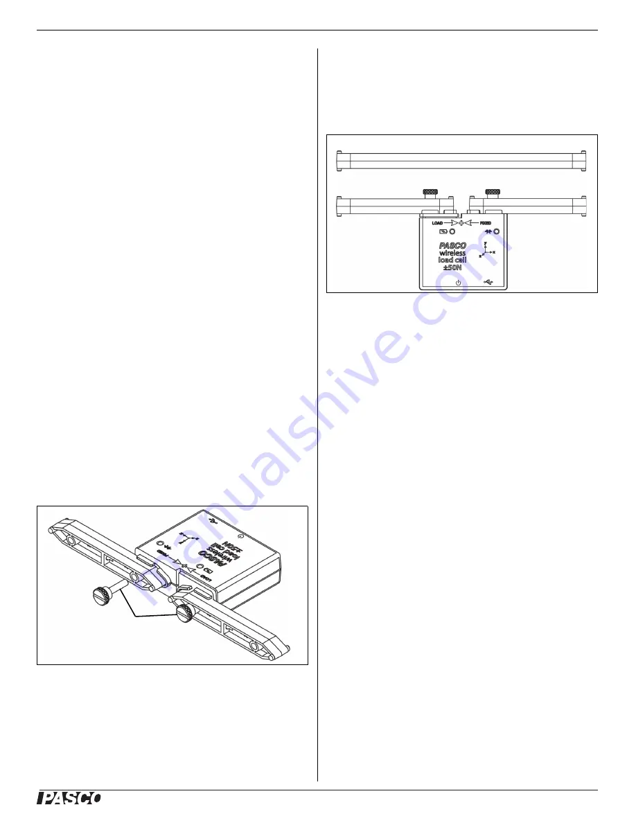
A Wireless Load Cell combined with two #2 beams is the 

same length as a #4 beam.

#5 beam = load cell + two #3 beams

#4 beam = load cell + two #2 beams

#3 beam = load cell + two #1 beams

Calibration of Wireless Load Cells

Wireless Load cells are factory calibrated; however, you 

can recalibrate them in software. See the documentation 

for your software for instructions.

When calibrating a Wireless Load Cell, it is necessary to 

apply a known load. Assemble the fixture shown in the 

figure below to support the Wireless Load Cell. Hold or 

#2 Beam

I-Beam

Thumbscrews

#2 Beam

#4 Beam

#2 Beam

Summary of Contents for PS-3216

Page 1: ...The PASCO Data Collection Software can show the compression or tension forces the accelera tion in X Y and Z and the resultant acceleration The sensor uses a micro electromechanical system MEMS device...

Page 2: ...he sensor off press and hold the ON OFF button for a moment until the Battery Status LED shines red The Wireless Load Cell puts itself to sleep after several minutes of inactivity if not connected and...

Page 3: ...tton All of the Force and Acceleration measurements will be set to zero To Zero Force or Acceleration Another option is to set either the Force measurement or the Acceleration measurements to zero Sta...

Page 4: ...option is to use the Common Rate button Click the Common Rate button in the Control palette below the workbook to open the Common Rate menu Select Wireless Force Sensor from the menu and then click th...

Page 5: ...th the PASCO Structures Systems such as the ME 3581 Building Better Bridges Kit The sensor can measure compression and tension forces in any member of the PASCO Structures Systems Use thumbscrews to m...

Page 6: ...Y Z Orientation In this orientation of the sensor the X axis direction is horizontal the Y axis direction is vertical and and the Z axis direction is perpendicular to the label on the front of the sen...

Page 7: ...rtant to making the sensor simple and always ready to use so all of the PASCO wireless products are designed for long battery life For example the sensor turns itself off after a few minutes of inacti...

Page 8: ...ence and 2 this device must accept any interference received including interference that may cause undesired operation CE Statement This device has been tested and found to comply with the essential r...

Page 9: ...hing lower than 0x6 means an older version of Bluetooth Your device will need the PS 3500 USB Bluetooth 4 0 Adapter 1The Mac Mini and MacBook Air were updated with Bluetooth SMART support in 2011 The...

Page 10: ...this example click 2 point 6 Click Next The Calibrate Sensor Enter Values screen opens 7 Hang the 1 kilogram mass on the calibration fixture 8 The gravitational force on the mass is pulling in the neg...

Page 11: ...linear equation that transforms the raw input data into the calibrated output data The linear function is of the form Raw Input Slope x Calibrated Output Offset Or Calibrated Output Raw Input Offset...

Page 12: ...e shifts so that it intersects the new point but its slope does not change Offset calibration is usually used to make one sensor agree with another sensor Due to normal variation among probes a second...

Reviews: