


®
Wireless Load Cell ±50N
PS
-
3216
2
013-15734A
See the PASCO Web page at
www.pasco.com/software
for help in selecting the right PASCO software and to
check the latest versions.
Software Help
See the SPARKvue Help or PASCO Capstone Help for
information about collecting, displaying, and analyzing
data.
•
In SPARKvue, select the HELP button (
) in any
screen including the Home Screen.
•
In PASCO Capstone, select PASCO Capstone Help
from the Help menu, or press F1.
Compatibility
Check the PASCO Web page at
www.pasco.com/compatibility
for the latest information on Bluetooth SMART
compatibility.
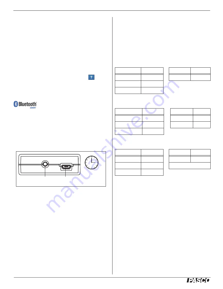
Initial Step: Charge the Battery
•
Connect the Cable: Use the Micro USB Cable to
connect the micro USB port on the Wireless Load
Cell to a USB port or USB charger such as the
PASCO PS-3501 USB Charging Station. Charging
begins automatically. The charger circuit inside the
sensor turns itself off when the unit is fully charged.
The battery status LED will shine yellow as the
battery is charging, and will shine green when the
battery is charged. The battery is partially charged at
the factory. Initial charging time may be three hours
or longer depending on the power source and the
condition of the battery.
ON/OFF Information
Press the ON/OFF button to turn the sensor on. To turn
the sensor off, press and hold the ON/OFF button for a
moment until the Battery Status LED shines red. The
Wireless Load Cell puts itself to sleep after several
minutes of inactivity if not connected and about one hour
of inactivity if connected.
LED Information
The Bluetooth and the Battery Status LEDs operate as
follows depending on the type of connection:
For a wireless Bluetooth connection:
For a micro USB cable connection to a USB
port
:
For a micro USB cable connection to a USB
charger
:
*Logging: PASCO wireless sensors can either stream
live data to a compatible device or log data inde
-
pendently (save it to the sensor’s on-board memory).
The data can then be uploaded to the device for display
and analysis at a later time. Logging capability supports
long-term or remote data collection while not connected
to a computing device.
Note: Both SPARKvue and PASCO Capstone support
logging. Check the PASCO Web page at:
www.pasco.com/software
for the latest software version. Please check the soft
-
ware on-line help (User’s Guide) for details about log
-
ging.
3 hours
USB port
ON/OFF Button
Bluetooth LED
Status
Battery LED
Status
Red blink
Ready to pair
Red blink
Low power
Green blink
Connected
Yellow blink
Logging*
Bluetooth LED
Status
Battery LED
Status
OFF
--
Yellow ON
Charging
OFF
--
Green ON
Charged
Yellow blink
Logging*
Bluetooth LED
Status
Battery LED
Status
Red blink
Ready to pair
Yellow ON
Charging
Green blink
Connected
Green ON
Charged
Yellow blink
Logging*